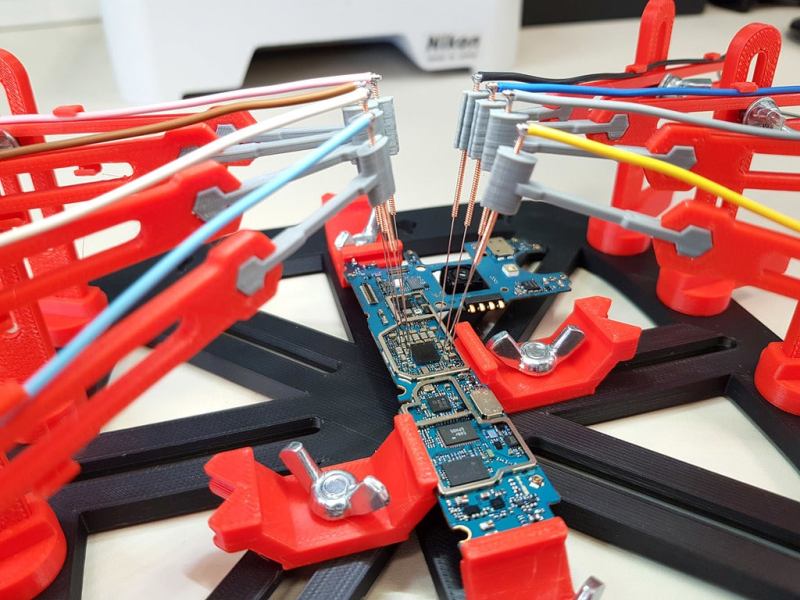
Trying to probe a modern electronic circuit with tiny SMD components, without letting the magic smoke escape in the process, can be quite a challenge. Especially since we hackers have not yet developed the number of appendages required to hold 3 different probes in place while operating both an oscilloscope and a computer. [Giuseppe Finizia] solved this problem with a 3D printed PCB probing jig that uses acupuncture needles.
As part of [Giuseppe] day job as an engineer at an electronic forensics laboratory, he does technical investigations on seized devices, which involves quite a bit of probing. The jig consists of a base plate with slots in which PCB holders of various configurations slide to hold all shapes and sizes of PCBs. Around the circumference of the plate there are multiple positions for adjustable probing “cranes”, each of which hold an acupuncture needle that is crimped or soldered to a wire. Each needle holder has a bit of flex which allows it to maintain downward pressure for a positive connection.
Making one-off tools and jigs is arguably one of the best applications for 3D printing, of which this is a perfect example. You can of course point solder wires or use test hooks if you have something to grab onto, but for easily probing multiple point on any PCB, this looks like a damn good solution. If you’re trying to trace a single signal, a precision pantograph might be your friend, or you can add a foot switch to your oscilloscope for quickly checking a circuit by hand.
[Jonathon Oxer] from the YouTube channel SuperHouse did a very nice video on the jig and made some small modifications. Check out the video after the break.


I can imagine that comming in pretty handy. Better than the ususal crocodile clip helping hands. The only improvements I’d suggest would be a ball and socket wrist to come in at an angle and heat shrink on the pins so only the tip is exposed. It would make it a lot easier to get around tall components, connect to adjacent points or to get to parts attached to heat sinks.
A ball and joint socket would be very handy for some situations, particularly when there are multiple connections close together. The probe mounts can get in the way of each other so being able to come in at a different angle would help a lot.
In the video I show heatshrink on the needles to prevent side-contact short circuits, but it also has the unexpected benefit that it makes the needles very easy to grip with a pair of SMT tweezers so they can be lifted and relocated.
I like this a lot. Our probe stations at work use a small vacuum pump, and each probe unit has a flat bottom with a vacuum line going to it and a little toggle to turn it off and on, so: position the probe where you want, and hit the switch, and it’s held in position. 3d printing vacuum tight may be an issue, but it might be worth considering as an extension to this.
I’d be tempted to add a living spring and a screw like dial indicator mounts use, to provide for very fine adjustment of needle height, eg for hitting die pads or metalization on decapped IC’s.
The use of acupuncture needles is genius. The whole project is fantastic. Our probe stations cost thousands of dollars. This easily replicates their utility.
Another option to hold the probe tip in place, is to apply a downward force on the probe tip. This could be done by putting a small torsional spring at the joint where the wing nut is.
Great design – I’m going to make one this weekend.
Rather than have the probes click into the plastic base, maybe a disc magnet in the base of the holder would snap to a metal plate – then you could place the probe gantries anywhere and easily move them out/in or rotate them.
That’s a great idea. I’ve been thinking about CNC-machining a base out of aluminium in the same style as the existing 3D printed design so that it adds some weight and has very accurate mounting holes, but having a flat steel plate with magnetically attached probe holders would be even better.
I think magnets might be too much effort.
I’d want a groove in the plate for the magnetic end to sit into – would make it far harder for it move accidentally without needing stupidly powerful magnetic fields (which seems like a bad idea in close proximity to electronics).
Then make the base end work on the same magnetic locking principle commonly seen for dial indicators which will make it even safer around electronics as it constrains the magnetic field.
Definitely going to be an improvement in convenience, but I don’t think its enough to be worth the extra manufacturing steps myself.
Simpler (and for me better) solution is giving the base more rail slots around the perimeter and use tapered threaded locks that expand the base when twisted. Same concept but reverse action of common scalpel holders with the twist you push the ends apart (a few other methods this concept can be made). If made for the same size as the PCB holder rails it opens up yet more spots you can mount both the holders and the probes for greater flexibility.
Great Project added to my ever growing list.. Might get to it around doomsday judging by current performance, damn does it take forever when you are juggling to much at once..
Those needles look a heck of a lot like guitar strings. Perhaps guitar strings could be a more readily available alternative for some folks?
they aren’t as firm as you would think. maybe some bass strings. but then were in too wide territory. perhaps if you do a heat treatment on them to stiffen them up.
I’ve been trying to probe a TSSOP part for a while now, this might be the ticket! Needles ordered!
I need one of those for jtagenum/jtagulator !
The traces on the scope showed strong ringing on the rising and falling edges. Adding 100-200 Ohms of resistance in series with each probe will reduce it. Start with a 330-Ohm pot and adjust it to the best compromise between low ringing and slower rising/falling edges. Then measure the resistance and put in a fixed resistor of the same value.
It would also be a good idea to run GND lines in parallel with each probe. When you work with fast or high-impedance signals, the parasitic inductance of the current loop from the probe tip to GND can pick up several volts worth of noise. Making the loop as small as possible reduces the problem.
microcoax (like you get between a laptop wifi card and the antenna) would be ideal for a BNC-terminated (or maybe SMB/A and an adaptor) would be more appropriate for probing higher speed signals straight into your scope. You could even add compensation like a scope probe for a better solution.
I’m totally building one of these jigs, anyway.
clever idea! Will shelve for future reference.
Next thing you know, the acupuncture community thinks they’re so great because they’re selling more needles than ever.
Btw, can’t you use piano or guitar strings, or are the smallest still too big?
I think the important thing here is how sharp acupuncture needles are. Music wire isn’t sharp.
If you go through the effort of sharpening music wire, I would instead suggest work hardened copper wire instead, as copper is a better conductor.
These particular acupuncture needles are stainless steel with the “grip” made of tightly wound copper wire. That copper wire grip makes it easy to make an electrical connection.
Dani,
what heat shrink product did you buy for this /
thanks pete
Where can i buy one of these?