Needling Your Projects: 3D Printed PCB Probing Jig Uses Accupuncture Needles

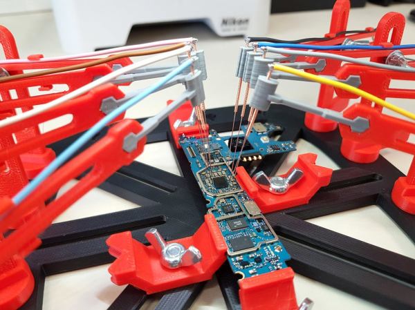
Trying to probe a modern electronic circuit with tiny SMD components, without letting the magic smoke escape in the process, can be quite a challenge. Especially since we hackers have not yet developed the number of appendages required to hold 3 different probes in place while operating both an oscilloscope and a computer. [Giuseppe Finizia] solved this problem with a 3D printed PCB probing jig that uses acupuncture needles.

As part of [Giuseppe] day job as an engineer at an electronic forensics laboratory, he does technical investigations on seized devices, which involves quite a bit of probing. The jig consists of a base plate with slots in which PCB holders of various configurations slide to hold all shapes and sizes of PCBs. Around the circumference of the plate there are multiple positions for adjustable probing “cranes”, each of which hold an acupuncture needle that is crimped or soldered to a wire. Each needle holder has a bit of flex which allows it to maintain downward pressure for a positive connection.

Making one-off tools and jigs is arguably one of the best applications for 3D printing, of which this is a perfect example. You can of course point solder wires or use test hooks if you have something to grab onto, but for easily probing multiple point on any PCB, this looks like a damn good solution. If you’re trying to trace a single signal, a precision pantograph might be your friend, or you can add a foot switch to your oscilloscope for quickly checking a circuit by hand.

[Jonathon Oxer] from the YouTube channel SuperHouse did a very nice video on the jig and made some small modifications. Check out the video after the break.

Endless Electronic Problems For Solving

We know not everyone who likes to build circuitry wants to dive headfirst into the underlying electrical engineering that makes everything work. However, if you want to, now is a great time. Many universities have most or all of their material online and you can even take many courses for free. If you want an endless pool of solved study problems, check out autoCircuits. It can create many different kinds of electronics problems and their solutions.

You can get a totally random circuit, or choose if you want to focus on DC, AC, two-ports, or several other types of problems. You can also alter the general form of the problem. For example, for a DC analysis, you can have it assign circuit values so that the answer is a value such as 45 ohms, or you can have it just use symbols so that the answer might be i4=V1/4R. You even get to pick the difficulty level and pick certain types of problems to avoid. Just be fast. After the site generates a problem, you have 10 seconds to download it before it is gone forever.

Continue reading “Endless Electronic Problems For Solving”

What’s The Difference? Ask An Op Amp

If you’ve ever wondered why an op amp has the little plus and minus symbols on it, its because at the heart of it, the device is a differential amplifier. The problem is that — ideally, at least — it has infinite gain so it works like a comparator and that’s not what you usually want. So we put resistors around the thing to constrain it and get useful amplification out of it. [Stephen Mendes] does the analysis for you about how the standard configuration for a differential amplifier works. He assumes you know the stock formulae for the inverting and non-inverting amplifier configurations and uses superposition.

[Stephen] mentions that’s the easiest way to do it and then goes on to do it sort of how we would do it as a check. We think that’s the easier method, but maybe its a matter of preference. Either way, you get the right answer.

Continue reading “What’s The Difference? Ask An Op Amp”