Surface mount devices can take some adjusting to for hackers primarily used to working with through-hole components. Despite this, the lure of the hottest new parts has enticed even the most reticent to learn to work with the technology. Of course, time rolls on and BGA parts bring further difficulties. [Nate] from SparkFun worked on the development of the RedBoard Artemis, and broke down the challenges involved.
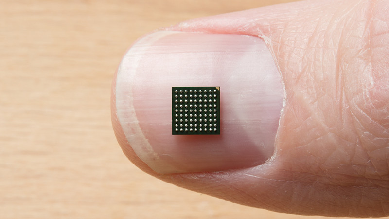
The RedBoard Artemis is an Arduino-compatible devboard built around the Ambiq Apollo3 chip. In addition to packing Bluetooth and 1 MB of Flash, it’s also capable of running TensorFlow models and using tiny amounts of power. The chip comes in an 81-Ball Grid Array at 0.5mm pitch, which meant SparkFun’s usual PCB fabrication methods weren’t going to cut it.
An initial run of prototype boards was run using 4 layers, blind and buried vias, and other fancy tricks to break out all the necessary signals. While this worked well, it was expensive and inefficient. The only part of the board that needed such fabrication was around the chip itself; the rest of the board could be produced with cheaper 2-layer methods. To improve this for mass production, instead, an SMD module was created to house the Apollo3, which could then be dropped into new designs on cheaper boards as necessary.
[Nate] does a great job of explaining the engineering involved, as well as sharing useful tips for others going down a similar path. So far, this is just part 1, with future posts promising to cover the RF shield design and FCC certification process. [Nate] has always been keen to share his wisdom, and we can’t wait to see what comes next!


It should be possible to make a bundle of insulated pogo pins, for example, from some really fine enamelled wire and just clamp any chip on top. As long as the wire diameter is smaller than the pins it wouldn’t matter where it touched them.
Breaking each one out to a larger diameter frame to represent their actual position is one thing. Like one of those optical fibre kids toys/mini Christmas trees, working out which pin goes with which wire would be tricky but in theory you’d have a universal breakout board.
Yup, exactly what automated testing stations do but while using pogo pins to connect to IC’s are great for prototypes and testing they not at all suitable for anything permanent or even semi-permanent.
If one needs to use a blind via with a part that small you don’t know what your doing. Blind vias kicks the PCB cost way, way up.
I’m assuming you didn’t read the article. But in the off-chance you did: Explain how you would avoid using blind vias.
*you’re. Oh the irony
Yawn. Any other stuff we could police?
How about floating chip above 2 layer PCB with flying wires? Encased in clear shell to protect chip and wires? If someone can do a 256 pin BGA, a tiny 81 pin BGA would be easy!
https://i.imgur.com/4rfTSyv.jpg
It’d be neat if we could actually access that image
Hot-linking causes the access denied -error. Reloading the page will get rid of it.
I’d love to do something with BGA’s but almost all of the packages have a pitch that prevent the PCB from being poolable in Eurocircuits for example, PCB’s are expensive enough, but paying an extra premium just to implement a BGA is not worth it for me at the moment. Maybe you guys have experience with other PCB services that allow such fine pitch footprints without paying an arm and a leg…
People have done 0.65 mm pitch with OshPark, there are several examples of Atmel SAM breakouts floating around. You can find a lot of BGAs with 0.8-1mm pitch as a start.