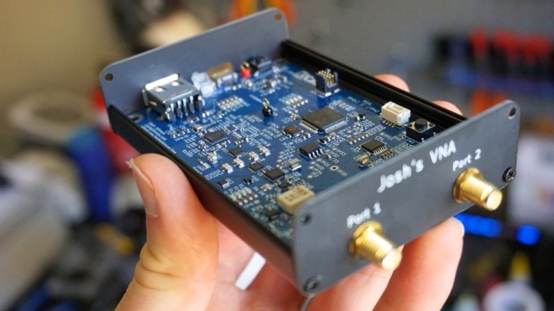
If you’re going to fail, you might as well fail ambitiously. A complex project with a lot of subsystems has a greater chance of at least partial success, as well as providing valuable lessons in what not to do next time. At least that’s the lemonade [Josh Johnson] made from his lemon of a low-cost vector network analyzer.
For the uninitiated, a VNA is a versatile test instrument for RF work that allows you to measure both the amplitude and the phase of a signal, and it can be used for everything from antenna and filter design to characterizing transmission lines. [Josh] decided to port a lot of functionality for his low-cost VNA to a host computer and concentrate on the various RF stages of the design. Unfortunately, [Josh] found the performance of the completed VNA to be wanting, especially in the phase measurement department. He has a complete analysis of the failure modes in his thesis, but the short story is poor filtering of harmonics from the local oscillator, unexpected behavior by the AD8302 chip at the heart of his design, and calibration issues. Confounding these issues was the time constraint; [Josh] might well have gotten the issues sorted out had the clock not run out on the school year.
After reading through [Josh]’s description of his project, which was a final-year project and part of his thesis, we feel like his rating of the build as a failure is a bit harsh. Ambitious, perhaps, but with a spate of low-cost VNAs coming on the market, we can see where he got the inspiration. We understand [Josh]’s disappointment, but there were a lot of wins here, from the excellent build quality to the top-notch documentation.


lost-cost? Very descriptive term especially if it’s a failed project!
Everything is low cost if compared to something expensive enough (e.g. a Teledyne LeCroy WavePulser 40iX (DC-40GHz Time Domain Reflectometers and
S-Parameter Analyzer ~$50k). The AD8302 (~$24) used at the heart of the above project operates between LF to 2.7GHz, so the comparison would be multiple orders of magnitude unfair (Even to just contemplate such a comparison :) )
Fixed it
I like reading about failed projects, and this one is particularly interesting to me.
I’m just getting into designing RF circuits, and just looking over the schematic and reading about the design decisions is informative. For example, I didn’t know that you could purchase a directional coupler in chip form, and reading about all the other hardware is one way to slowly fill in background information.
I’m trying to breadboard a big coil and capacitor to handle 600 watts for dielectric heating. I’ve made several attempts, none have worked so far…
Anyone have a good reference for physically constructing a power LC circuit? Not the equations or the theory, but practical matters such as mounting, heat dissipation, stray capacitance, and dealing with ultrahigh voltages.
(Alternately: Anyone want to hire out to build a bespoke system for me? I have some spare cash…)
Look up how to build a solid state Tesla coil.
Specifically Class-E Tesla coils. These are coils that deal with high frequency. [PWalsh] asks for 13MHz below.
More background: I own a (variable output) 600-watt RF generator, so I’m only looking to make the passive section of the design. Effectively a dummy load that matches the generator 50-ohm output to a 2.5 ohm load.
I have several times designed a circuit, simulated it in Qucs to verify the response, and made a physical build. I know how to design an impedance-matching circuit from scratch without looking it up.
My problem isn’t in the theory or the equations, or the simulation, or the active components, or not having looked online for similar solutions. Tesla coil builds don’t deal with impedance matching, and high voltage coils are not closely similar to high voltage capacitors.
My problem is in the execution, I have some money set aside, and I’d like to hire someone to do it or show me how.
So low current (low inductive coupling), extremely high voltage, and similar in effect of operation, but not the actual details – since it is not using microwaves, to a 2.45 GHz microwave oven. And with a wavelength large enough (~23m / 76 feet) that you could even use cheap mesh fencing wire for attenuation shielding to reduce the RF to a safe level outside of the device. Sounds like a dangerous project.
Here’s an example of what I’m trying to do. The simulation shows all 600 watts being delivered to the dielectric (Rdia), so this should work.
When I build the L1/C1 alone, without the RF generator and the impedance-matching capacitor, and test it the relf-resonant frequency is below 12 MHz. The coil measures out as the right value, it’s built to minimize capacitance, and I don’t know what’s wrong.
(I’ll put this up on the stack at IO in a few minutes.)
https://cdn.hackaday.io/images/1910011577821440727.png
Not sure this is what you are looking for but it might have some helpful information that you can scale down to 600 watts http://inductionheatertutorial.com/
That’s a good site, but induction deals with massive current, while dielectric heating deals with massive voltage. Probably several tens of thousands of volts, and construction details for those types of circuits are different.
Also, induction heaters run at several hundred thousand Hz, while I’m looking to do this at 13 MHz, and have to deal with impedance matching (of the 50-ohm output generator to the 2.5 ohm dielectric load), reflected power, and other RF details.
Dielectric heating is done all the time in industry, most notably to heat bakery products, so I know there are existing solutions. I just need to find someone with expertise in RF power design.
You keep saying you want to match 50 ohms down to 2.5, which would reduce voltage and increase current – and then say “high voltage” over and over. Did you get a ratio upside down somewhere?
The circuit is an impedance match feeding into a load which is an LC with the dielectric to be heated. At resonance the LC complex impedance cancels, leaving the lossy dielectric remaining as a (real) resistance of about 2.5 ohms. This is what the RF generator sees, so the intervening circuit has to match the RF output impedance to the dielectric effective resistance.
At resonance, the voltage across the C will be Q times the input voltage to the L-C pair, and the current through the L will be the Q times the input current. These are out of phase and cancel, so none of this gets out and into the rest of the circuit, but measured individually the L-C stage capacitor will have enormous voltage.
This image shows a simulation, with the C2 voltage at about 30 KV.
https://cdn.hackaday.io/images/1910011577821440727.png
(If the dielectric resistance is 2 ohms, the C impedance at resonance is about 2K ohms, so the voltage across the C will be around 1000 times the L-C input voltage (Q = 2k/2 = 1000). 600 watts into 2 ohms is about 34 volts, so voltage across the C should be 34*1000 = 34 kV. This disregards stray resistance in the coil, which will bring the voltage down a bit in any real circuit.)
(Also, since the effect I’m looking for is proportional to electric field (squared), I design for the smallest practical capacitor – giving the highest impedance at resonance – to generate high voltages.)
BTW, definitely a fan of your work. From looking at your published stuff, think you’d really appreciate the end-purpose of this experiment :-)
More info here:
https://hackaday.io/project/5283-potpourri/log/172528-need-help-building-a-dielectric-heater-for-science
If you haven’t played with RF, build something lower power first and learn from it. Use LTSpice to simulate and that should at least tell you a bit how the circuit would behave.
Look into the way that a transmatch/balun/unun works for Amateur Radio. There a plenty of designs for 12:1 baluns floating around, some of which handle 1 or 2 Kilowatts. It should be fairly easy to modify the design process from 14Mhz(aka 20 meters) to 13Mhz.
13.56MHz is used all the time in industrial heating applications. Typically it needs a RF matching network to make up for the changing impedance of the RF load. Many matching network types (LC, CL, Pi) are around and do a good job of fixing unknown capacitances and inductances. They also will make up for a range of resistive load differences, but you might need to introduce a transformer into the output stage. There are a number of papers around on the web – I just looked up one that I’ve referenced before titled “Matching Networks for Power Amplifiers Operating into High VSWR Loads” by Richard W. Brounley. Also, you need to measure forward vs reflected power (MKS amplifiers have this built into them) and I’d be careful with Q as the voltages can get high even in low Q circuits. Get it working first and then you can tweak the Q. Find a RF guy (or ham radio operator) to help.
Awesome senior project! I am all for an ambitious project and it’s nuances that come along with the failures.
Very fine attempt and neat layout, but his problem of low dynamic range and severe sensitivity to harmonics is because he is not doing any form of narrow band detection! The RF is sampled straight into a broadband Gain-Phase detector and not mixed down. If he only mixes it down atleast once, filters and then samples the architecture should have worked I feel.