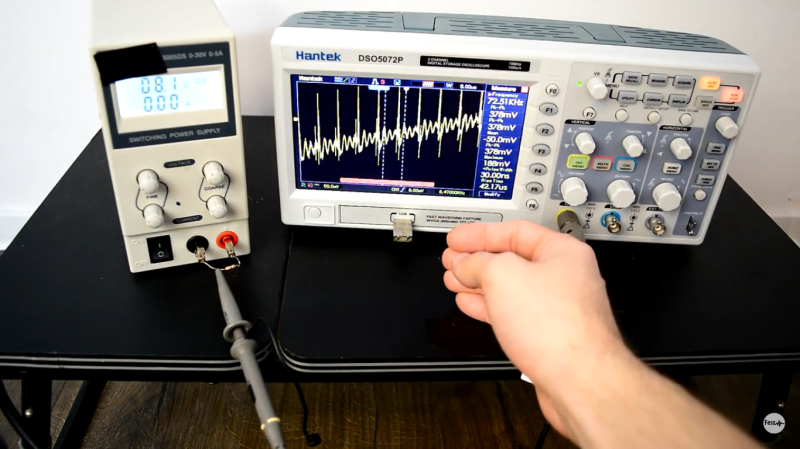
Grounding problems and unwanted noise in electrical systems can often lead to insanity. It can seem like there’s no method to the madness when an electrical “gremlin” caused by one of these things pops its head out. When looking more closely, however, these issues have a way of becoming more obvious. In a recent video, [Fesz Electronics] shows us how to investigate some of these problems by looking at a small desktop power supply, modelling it in LTSpice, and reducing the noise on the power supply’s output.
While everything in this setup is properly grounded, including the power supply and oscilloscope, the way the grounding systems interact can contribute to the high amount of noise. This was discovered by isolating the power supply from earth ground using electrical tape (not recommended as a long-term solution) and seeing that the noise was reduced. However, the ripple increased substantially, so a more permanent fix was needed. For that, the power supply was modelled in LTSpice. This is where a key discovery was made: since all the parts of the power supply aren’t ideal, noise can be introduced from the actual real-life electrical behavior of some of the parts. In this case, it was non-ideal capacitance in the transformer.
According to the model, this power supply could be improved by adding a larger capacitor across the output leads, and also by increasing their inductance. A large capacitor was soldered in the power supply and an iron ferrule was added, which decreased the noise level from 100 mV to around 20. Still not perfect, but a much needed improvement to the simple power supply. If, on the other hand, you want to make sure you eliminate that transformer’s capacitance completely, you can always go with a transformerless power supply. That carries other risks, though.


Play much golf?
Learn to use a ground spring instead of that alligator clip when measuring noise?
Very few are even aware of the ground spike (spring) shipped with almost every cro probe made, let alone what it is used for.
Wow, mind blown.
I never one was was included anyway, found out in the last years from the YouTube videos. I bought about 3 cheap probes, got another 5 or so with various equipment, none of them had those springs. They do have colored rings though and a small plastic screwdriver.
Hmmm. So not every cro probe made then. But you know about the ground springs which is more than I can say for the vast bulk of my colleagues who are also, as it happens, degree qualified engineers. I know I didn’t learn about them at uni. Maybe the others since graduating have been too busy flicking the propeller on their baseball caps to notice them and ask… ;-)
The small plastic screwdriver I learnt about from a tech who did old school CRT tv repairs. I would say it was another thing few know about but now I’m not so sure how correct that would be.
The coloured rings are useful. Love the coloured rings. :-)
> this power supply could be improved by adding a larger capacitor across the output leads, and also by increasing their inductance.
That’s a pedestrian way of saying a PI filter.
>If, on the other hand, you want to make sure you eliminate that transformer’s capacitance completely
You can minimize the inter-winding capacitance by either:
– a ground shield layer between the two windings.
– transformer with windings located on opposite sides.
You think you can eliminate the transformer capacitance completely!!!???
A large electro with inductance (I assume ESL) does not a pie filter make. More of a notch filter as the capacitor and its inductance form a series LC load.
Ground shields are not so common in SMPS and separated windings as you suggest while still not eliminating capacitance will for sure introduce a leakage inductance that would render the power transfer capability of the transformer null and void (or thereabouts) and leave the designer researching lossless snubber circuits because of the enormous back emf from the leakage inductance. It is virtually impossible to do this in an SMPS unless the topology is some funky resonant thing that exploits the leakage inductance but that is doubtful.
The art of SMPS transformer design is in the first instance balancing the leakage inductance and the capacitance (inter and intra winding), copper (skin and proximity effects) and transformer core losses, output smoothing filter (inductor value and size), the switching frequency and the switch and diode speeds and whatever snubber circuits might be required depending on the topology etc etc etc. Adding a ground shield is in my experience only ever done in SMPS if there are issues with meeting the creepage and clearance requirements. Most manufacturers seem to shy away from a protective earth connection (although many do seem to like functional earth connections).
A lot of the noise can be generated by the reverse recovery of the rectifiers which can be exacerbated by faster switches and the intra-winding capacitances if they are not properly snubbed.
I will confess now, I have not watched the video. I just read that post and had to say something, like I do! ;-) No offense intended in any way.
I didn’t watch the video so I’m guessing that it demonstrates all the advantages of a linear PSU.
I think the YouTube channel “The Stuff Made” had a more interesting fix for these cheap Chinese power supplies. It may even pre-date this one though I am not sure. Putting larger caps in the output does not really fix the source of the noise…
More to the point, an SMPS with a voltage mode control loop can be dependant on the output capacitors having a certain amount of ESR to generate a zero in the transfer function and thereby keep the converter stable. Capacitors after the output EMI filters should be ok but a point worth keeping in mind if doing this (check stability, besides the obvious erratic switching, step load response is your friend!).
Capacitance multiplier when things go mad… Done
A big cap across the output bears other risks, one of them being that the capacitor will briefly allow drawing way more current than the PSU’s limiter would allow.
Buy a good bench power supply and not a cheap shit one. You find you get what you pay. So you buy cheap then it’s not going to be great. Buy a nice power supply then it’s going to give you good results. I know you can improve that cheap power supply but just look at it? It’s all cheap parts inside and even some of it can be fake parts like the capacitors,etc. The amount of fake capacitors I see now is mad and when tested show shocking results.
^ This. 0.1V of ripple for a power supply is not acceptable whatever the price. Having to spend days in electronic debugging just because you’ve decided to save 50$ on the PS is dumb.
On the other hand, you might learn something trying to fix or improve a shitty product.
Exactly. The learning gained while getting dirty hands.
But this is the difference between a hackers ‘kit’ and a professional lab. Horses for courses as they say.
Stop buying Chinese garbage.
Just take off glasses and all the noise on the scope blurs a bit.
LOL
Nice one! :-)
Grounding the negative of the cheap poet supply eliminates a lot of noise and suppressing the input grounding.
Part of nasty noice comes from the dirty electricity!!