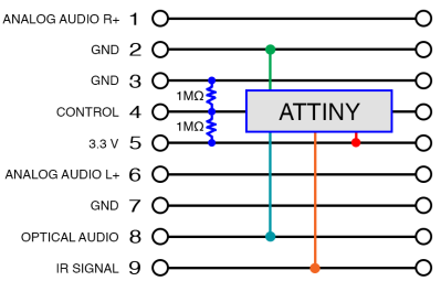
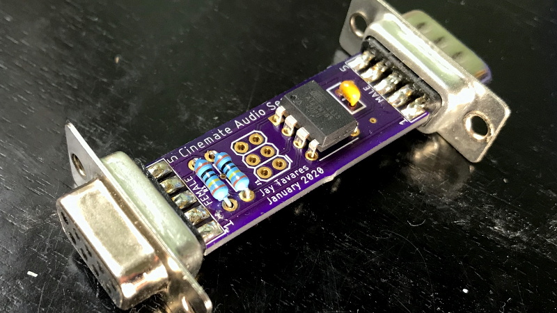
Like many of the stories you’ll find on these pages, this one starts with a user being annoyed about their device’s inability to perform a simple task. All [Jay Tavares] wanted was for his Bose Cinemate speakers to turn themselves on and off as needed. It seems like a reasonable enough request, and indeed, is exactly the point of HDMI’s Consumer Electronic Control (CEC) feature. But in this case, it would take a bit of custom hardware to get similar functionality.
Unfortunately, the speakers [Jay] has only support optical audio; so any interoperability with HDMI-CEC (hacked or otherwise) was immediately out the window. Still, he reasoned that he should be able to detect when the TOSLINK audio source is actually active or not, and give the speaker system the appropriate signal to either power on or shut down. You might think this would require some kind of separate stand-alone device, but as it turns out, all the necessary information was available by reverse engineering the connection between the receiver and the subwoofer.
 After some investigation, [Jay] found that not only was the content of the TOSLINK audio source being sent over this DB9 cable, but so were the control signals required to turn the system on and off. So he designed a simple pass-through device with an ATtiny85 and a couple passives that latches onto the relevant lines in the cable.
When audio is detected over the optical connection, the MCU will inject the appropriate signals on the control line to simulate the user pressing the “Power” button the remote. When the chip hasn’t detected audio after 10 seconds, it sends the signal to shut the speakers off.
While [Jay] notes he can’t guarantee this works on anything other than the particular Bose Cinemate GS Series II system he has, we’d be willing to bet the concept could be adapted to other models or even brands that use a similar cable to link their principle components. If all else fails, you could always add an ESP8266 to your sound system and control it over WiFi.


Nice hack!
I have the same kind of problem with my firetv 4k (connected to a video projector), when the firestick is put in standby, it does not send the standby order through hdmi, but instead just shows a black screen which won’t put the projector in standby. Not sure why they would do that. That’s one of my two issues with the firestick, the other one is that there’s no way to actually control the audio output volume… It only works by sending IR commands to whatever device it’s connected too (so it doesn’t work with an hdmi computer monitor for example)
similar problem here. I’m using a samsung 4k tv for a monitor and even though it has PC mode it wont turn off when the pc sends the signal to sleep. I messed around with an attiny on usb emulating an ir remote but never completed it.
Graphics cards rarely support HDMI-CEC.
But there is DDC https://en.wikipedia.org/wiki/Display_Data_Channel
Fwiw Nvidia gtx 1070 does. PC sleeps, then displaying/tv sleeps, then audio sleeps.. extremely annoying because on wake, applications don’t recognize audio anymore until they are restarted.
In my homemade Pinball cabinet (Visual pinball, emulation) the tv I use for a backglass refuses to wake up when the pc that runs the show starts.
My solution, El cheapo chinese arduino knock-off. I “recorded” the right buttons pressed on the remote and now an arduino “presses the buttons” a certain time after power-on.
It has to be a waiting period after power-on I geuss the tv has to boot some sort of os in order to process the remote commands.
It then sends the commands through an ir-diode tucked away within line-of-sight of the tv’s ir-sensor.
Have you made sure HDMI-CEC is turned on on both the Fire stick and your projector?
It would be interesting on the investigation part. The actual mod probably is different from each vendor.
Well done project! And it comes with very neat and comprehensive documentation. I especially love that he looked at the requirements first and thought a moment before he started doing things like “So I took a Raspi 3 and installed some python libraries…”. Since this couldn’t have been done with a 555, it totally makes sense to use an ATtiny.
That raises the question, what you COULD do this with?
Injecting the signals into the IR line are likely to be the most tricky.
I had a working modchip (unrelaible) for early PS1 models that injected the region code (which also handled copy protection).
It basically worked like this https://www.reddit.com/r/diyelectronics/comments/4tmvia/quick_project_to_read_eeprom_data_without_using_a/
The PS1 copy protection is discussed in the comments here, https://hackaday.com/2018/11/05/how-the-sony-playstation-was-hacked/
I was scant on details at the time and I’m afraid I’ve recalled even less now it’s 2020. It basically injected “SCEA” or whatever the region code was into a serial bus on the motherboard. It wasn’t very smart (it ran constantly and was detectable by later games) which is why I still (in the past week – again!) use swap magic. It’s the only way I can play FFXII IZJS with a language patch.
That should read I use swap magic on the PS2 to play FFXII. Not the PS1. Guess I haven’t played it in a while.
Why not just detect the IR light in the Toslink? No light? Off. Light? There could be a solution here with a timer and light detection circuit – not taking away from the author’s work. Multiple ways to skin it. Why not make this a 555 challenge?
This was my original plan, but the only way to “see” the light is to have a separate box with TOSLINK in and out. I chose this approach since it was the simplest/cleanest. The DB9 connection at the sub woofer provides the perfect location with access to everything you need. Out of curiosity, how would you handle the power-on/power-off functionality using a 555?
I wonder if we’ll see similar hacks for Sonos kit, given their recent announcement regarding “recycling” their older speakers: https://www.bbc.co.uk/news/technology-50948868
Sonos never ceases to amaze me… *smh*
To Sonos’ credit they backed off of that. Here’s an email I got from them
– – – – – – – – – – – – – – – – –
We heard you. We did not get this right from the start. My apologies for that and I wanted to personally assure you of the path forward:
First, rest assured that come May, when we end new software updates for our legacy products, they will continue to work just as they do today. We are not bricking them, we are not forcing them into obsolescence, and we are not taking anything away. Many of you have invested heavily in your Sonos systems, and we intend to honor that investment for as long as possible. While legacy Sonos products won’t get new software features, we pledge to keep them updated with bug fixes and security patches for as long as possible. If we run into something core to the experience that can’t be addressed, we’ll work to offer an alternative solution and let you know about any changes you’ll see in your experience.
Secondly, we heard you on the issue of legacy products and modern products not being able to coexist in your home. We are working on a way to split your system so that modern products work together and get the latest features, while legacy products work together and remain in their current state. We’re finalizing details on this plan and will share more in the coming weeks.
While we have a lot of great products and features in the pipeline, we want our customers to upgrade to our latest and greatest products when they’re excited by what the new products offer, not because they feel forced to do so. That’s the intent of the trade up program we launched for our loyal customers.
Thank you for being a Sonos customer. Thank you for taking the time to give us your feedback. I hope that you’ll forgive our misstep, and let us earn back your trust. Without you, Sonos wouldn’t exist and we’ll work harder than ever to earn your loyalty every single day.
If you have any further questions please don’t hesitate to contact us.
Sincerely,
Patrick
Patrick Spence
CEO, Sonos
A rather typical problem to occur in any multiroom / home theater setup and a neat solution for it!
Pet peeve of mine.
It’s a DE-9 connector. DB specifies the 25-pin sized shell, and the smaller obsolete 19-pin variety once used by Apple.
https://en.wikipedia.org/wiki/DE-9
Nobody cares.
Funny story: I actually made the conscious decision to call it a DB-9 in my write up to avoid confusion since I more often see it referred to as such. If you download the Eagle files, you’d see that the custom footprints I created for the board edge mounted connectors use the correct name. Though, I’ll admit that I only just discovered over the course of this project that I’ve been erroneously referring to these as DB-9s for many decades. 🤦♂️
I especially liked the soldering of D-Sub9 solder buckets directly to PCB pads!
How can an ATTiny detect an optical signal ? I have a feeling the denomination is simply wrong..
Check out the theory of operation section in the github repo. There’s a toslink connector in the interface module that converts the light into data on wires. The attiny is looking at that data.