[René Ceballos] contacted us about the new XFM2 FM synthesizer board, successor to the XFM that we covered on Hackaday last year. In addition to changing FPGAs from a Spartan 6 to an Artix-7 35, the DAC was also upgraded from 16 to 24 bits. Since the project is based around two easily available boards for the FPGA and DAC functionality, it is something that should be easy for anyone to recreate.
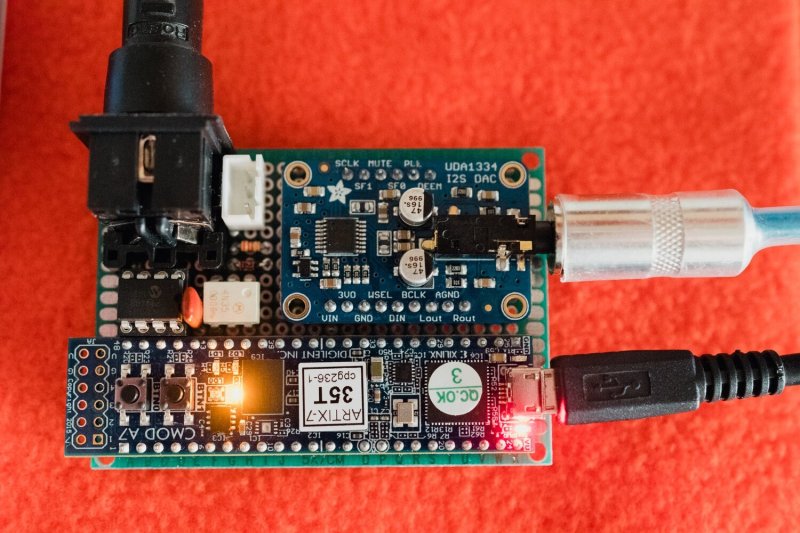
The project consists of a lower board that features the opto-isolated MIDI-input port, a 24LC1025 EEPROM, and a few passives, on top of which are mounted the Adafruit UDA1334A-based I2S decoder board and a Digilent Cmod A7-35T, containing the Xilinx XC7A35T-1CPG236C Artix-7 FPGA. [René] has made a schematic and BOM available on the XFM2 page. Total part cost should be about $99.
A user manual, installation guide, and the binaries that have to be loaded into the FPGA – using the provided instructions – are all made available. Unfortunately no HDL source is provided, but that shouldn’t take away from the fun of assembling an FM synthesizer board like this.
[René ] said that based on the feedback to the XFM project, he is now working on a visual user interface for the board. Once this is all working and depending on the feedback from XFM2 users, he may decide to start a crowdfunding campaign.


The user manual indicates the amplitude envelope has a sample rate of about 60khz, for about 32 channel polyphony.
I wonder what sample rate would be possible for fewer waveforms, i.e. could this be used for direct synthesis of morse, psk, wspr, bpsk or qpsk in some of the vlf or lf bands.
The problem would be the DAC. It’s an audio I2S device so you’ll be limited to roughly 48KHz max. You should be able to use the FPGA to generate modulated RF at anything up to a few MHz, providing you use a fast-enough DAC (even a simple R-2R ladder may be good enough).
This fpga can easily generate 100MHz wide OFDM for example.
Most audio DACs easily do 192 kHz today. I would argue there are no true 24 bit DACs (at the analog output at audio rates). Check Audioscience Review DAC forum.
Youse guys is poivoise I says….
On another post there’s Jim tryna turn gnu radio stuffs into a synth and here’s this tryna turn a synth into radio stuffs.
Ima do a project to weld the tines of a fork together to make it into a spoon, and grind slots in a spoon to make it a fork, and submit it, that should go down well. :-p
Honestly im 100% going to steal this idea .
And I just re-watched Mike Ossmann and Kate Tempkin’s talk where they take an accelerometer, run the data through GNURadio, and make a horrible guitar pickup and distortion effect.
What the heck is with all the people doing strange things here? Why can’t anyone just leave the poor electronics alone?
Found a vid: https://www.youtube.com/watch?v=fJyIRA1ev-A
Artix 7. If I remember correctly (or Misremembering) that is the next Gen that uses Vivado. And not the ISE studio. The Gen 6 chips Spartans (common with those Panologic gems) Logic Gates
147,443
Memory (Kb)
4,824
DSP Slices
180
3.2 Gb/s Transceivers
–
Maximum I/O
576
Artix 7
Logic Gates
33,280
DSP Slices
80
Memory
1,800
GTP 6.6Gb/s Transceivers
4
I/O Pins
250
I know you a little bit about the ISE Design (like for Win 10 it can do all the big Spartan 6 chips now. And I think they are making the push or stock is finally running out for the spartan 6?
Vivado? Even less.
There were some tools to get a Vivado file pushed to a Spartan 6 using some C and python magic.
For dumping and existing image? Again my gap in knowledge grows. I did find this however.
https://kevinpt.github.io/hdlparse/
God Speed Electronic Babbage Heros!
P.s. Did anyone get an FTDI dead bugged to any of those Panologic gen 2/gen 3? For a proper USB controller so it wouldn’t eat any Fabric?
The HDL for the FPGA is still closed source.
“Dang those nine ten does. They don’t even have the pins labeled for those jtag connectors” sshhh, it will be okay. Go back to sleep.
Yeah. This is a bummer. I don’t need any more FM synths, but I _do_ need nice code examples.
“Since the project is based around two easily available boards for the FPGA and DAC functionality, it is something that should be easy for anyone to recreate.”
It would also be easy to say things in words the first time like any style manual will tell you to do rather that dive right into all acronyms all the time (AAATT). Be best.
Maybe we could get a LUT to address the FAQ about TLAs
Wow… I would say that for the target audience that FPGA and DAC are no longer considered acronyms in need of initial definition much as no one worries about defining RADAR, LASER, SCUBA, CPU, and RAM.
Indeed, everyone should know what a Field Pwnable Gloop Adapter is by now.
Dang those pesky kids and their pentodes we had triodes and didn’t need nuffin else!
I am a tetrode guy myself.
“When I was a kid, all we had were light bulbs, and we made diodes by adding some foil to the glass.”
i don’t get it, how is this different from just a softsynth running on the PC? is the motivation performance?
I don’t know if you noticed, but it is a tad smaller and likely to be lower power. Musicians are also a picky bunch, they don’t like whooshy fan or whirry drive noises getting picked up by the studio mics.
FPGA’s are essentially hardware emulations of real chips. This can be more authentic sounding than a soft synth, depending what you’re going for. What I’m not clear on is if this is actually a recreation of a real 6-OP Yamaha chip like that of the DX7.
This isn’t an exact clone of a DX7 it’s better as for a digital synth sounding more Authentic on a FPGA than any other processor or softsynth I think you don’t really understand digital.
Guaranteed performance, and can be used without a PC. Though for serious use it would need a case, and a redesign with connectors that won’t shear off.
In this case the FPGA should allow for a internal sample rate up in the MHz, avoiding the aliasing issues that VST’s and older hardware FM synths are prone to.
About how much would this cost?
$99
solution to this being closed source is to port Dexed to ARM COrtex M7 and loling hard
Make that 5 M7s @400M for getting barely close to the glops, and forget about battery life before loling :-)