Do you need portable power that packs a punch? Sure you do, especially if you want to light up the night by mummifying yourself with a ton of LED strips. You aren’t limited to that, of course, but it’s what we pictured when we read about [Jeremy]’s Thunder Pack. With four PWM channels at 2.3 A each, why not go nuts? [Jeremy] has already proven the Thunder Pack out by putting it through its paces all week at Burning Man.
After a few iterations, [Jeremy] has landed on the STM32 microcontroller family and is currently working to upgrade to one with enough flash memory to run CircuitPython.
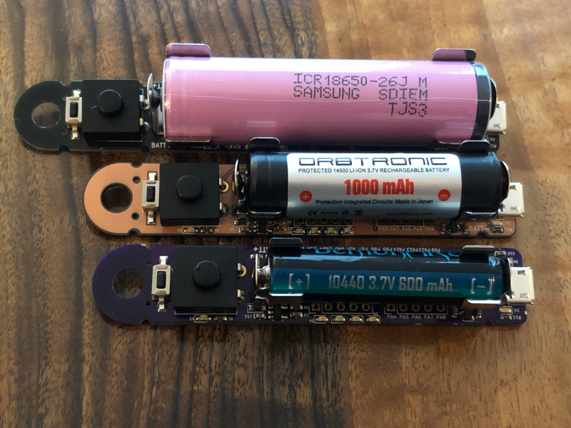
The original version was designed to run on a single 18650 cell, but [Jeremy] now has three boards that support similar but smaller rechargeable cells for projects that don’t need quite as much power.
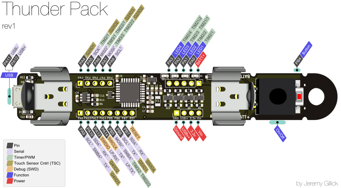
We love how small and powerful this is, and the dongle hole is a great touch because it opens up options for building it into a wearable. [Jeremy] made a fantastic pinout diagram and has a ton of code examples in the repo. If you want to wade into the waters of wearables, let whimsical wearables wizard [Angela Sheehan] walk you through the waves.


How much do they weigh? Wondering if PoEoAC works yet.
Probably only slightly more than the weight of the battery.
The standard size (18650 battery, 3400mAh) is roughly 57 grams and the small size (14500 battery, 1000mAh) is about 30 grams.
Neat idea. I’ve got all sorts of uses for those.
Without seeing the schematic: it looks like the output is limited to battery voltage. It seems that it should be possible to run the micro off the local battery and the actual lights off (say) a 12V pack, so you could use COTS light strips.
Mostly, yes. The output is limited by both the battery capacity and the Mosfets. The FETs (BSS806NH6327XTSA1) are each rated at 2.3A, however, the GPIO opens them to ground, so you could theoretically run a higher voltage through them.
But then I would include a small step down converter to run the MCU also from the main pack. I once did a control unit for LED strips (and some more, including zigbee) on costumes. I ran the LEDs of 2* 2s LiPo rc model batteries (800 or 1000mAh) and the CPU even measured the battery voltage to compensate for the voltage variation by PWM dimming of the LEDs.
I have no idea, why my previous comment went to moderation and was obviously killed. I just suggested to use a step-down converter for MCU to use only one battery and that I did just that in a former project. I used two times 2S Li packs and did some software correction for the battery voltage variation by PWM.
Uh, using those battery clips using lithium cells is asking for big trouble in your pockets, at least when having keys in them too!!!
Whatever the clips there’s the whole rest of the unprotected PCB to worry about unless you case it.
Probably that’s why the project author mentions cells with built-in protection.
What’s funny is that part of the reason why I used cylindrical batteries in this design is that they’re more rugged for wearables than the silver pouch cells that can explode if bent (i.e. in pockets). I found that heating a short length of shrink tubing around it provided protection from shorting and was a cheap and simple enclosure.
I’m currently exploring other battery terminals too.
The battery terminals are not the only issue. It’s an unprotected piece of electronics. I would use it on the lab table, but not as a wearable. It needs some case or at least put it into a piece of PVC pipe used for electrical installations. OK, you do not need to take out the battery to charge it, so shrink tube is OK. But then you can use a battery with solder tabs and no clip contacts.
Yup, battery with solder tabs would work fine…however, they’re usually not sold with protection circuits built-in (at least that I’ve seen). I required the protection circuit to be built-in to the battery to keep the overall PCB size down. It only makes the battery a few mm longer. But if you have a battery with protection and tabs, then that wouldn’t be a problem at all and the PCB would be trivial to update to support it.
As for the PCB shorting, generally you don’t put wearable PCBs in the same pocket as your keys anyways. It would work better in the inside jacket pocket or a little pouch made for it. Either way, these are all pretty solvable problems either with shrink tubing, enclosures or wearable placement.
It would be nice to see a way to purchase these. Kickstarter or Tindie?
That’s the plan. I’m finishing up testing the STM32F4 chip and then will order a small run that I’ll put on Tindie. That should happen soon. Stay tuned.
Why u chosen an STM32 uC and not an Arduino Core uC ? The Arduino Core Firmware is already done
I wanted this platform to be able to go beyond Arduino, if necessary. I could have gone the ATSAMD line of chips, but felt drawn to the STM32 line. Overall, though, getting it to work with Arduino was probably the easiest part of the project. CircuitPython was a bit more difficult.
I did not have a close look on the features but I think such a small device should need not more than an STM32F1 chip. What’s the reason for the big one?
A few factors went into chip choice: cost, physical size, usb bootloader, and flash size.
Physical size: To keep the board small, the chip needed to be 7x7mm or smaller.
USB bootloader: likely self explanatory.
Flash size: This was the stickiest part. CircuitPython needs 512k minimum.
The STM32F1 chip with 512k is 10x10mm and doesn’t have a built-in USB bootloader (STM32F100).
The original chip was a STM32L07. It was small (5×5), low power, and worked really well. Unfortunately, it didn’t have enough flash memory to support CircuitPython. Since CircuitPython is gaining in popularity and is a really great ecosystem for people getting into microcontrollers, I wanted to make sure this platform could support it and upgraded.
The STM32F4 is truly overkill for most things and I’m excited to see how far people can take it.