How much easier would life be if you could just grab hold of whatever mechanism you wanted to manipulate, move it like you want, and then have it imitate your movements exactly? What if you could give a servo MIDI-like commands that tell it to move to a certain location for a specific duration? Wonder no more, because [peterbiglab] has big-brained the idea into fruition.
With just one wire, an Arduino, and some really neat code, [peter] can get this servo to do whatever he wants. First he tells the Arduino the desired duration in frames per second. Then he grabs the horn and moves it around however he wants — it can even handle different speeds. The servo records and then mimics the movements just as they were made.
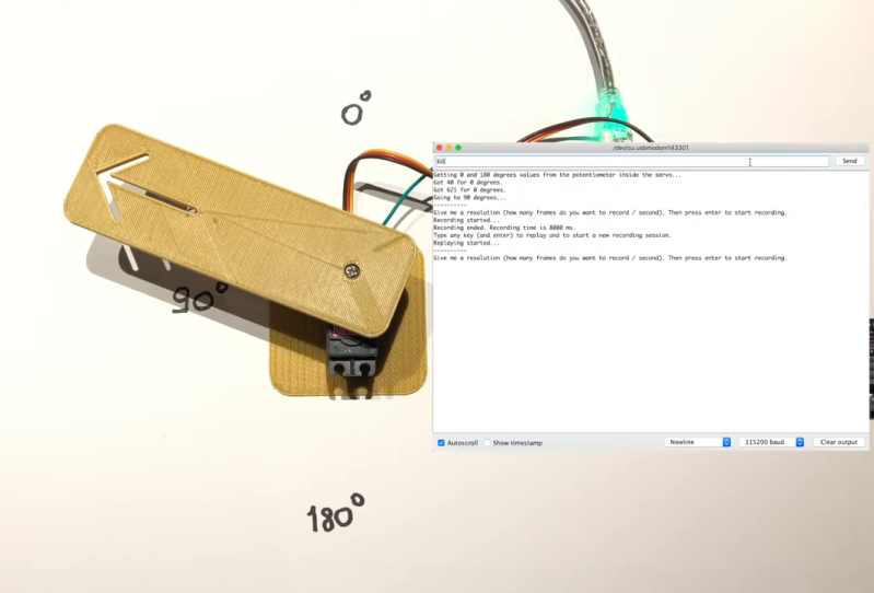
The whole operation is way simpler than you might think. As [peterbiglab] demonstrates in the video after the break, the servo knows its position thanks to an internal potentiometer on the motor’s rotor. If you locate the pot output pin on the control board and run a wire from there into an Arduino, you can use that information to calibrate and control the servo’s position pretty easily. There are a ton of possibilities for this kind of control. What would you do with it? Let us know in the comments.
If you want to try this with a bunch of servos at once, might as well build yourself a little testing console.
Via r/Arduino


This already exists.
Well yah, they’re not writing about things that haven’t happened yet, yet, crystal balls are hard to interface so they’re still waiting for the arduino shield.
You’re a funny guy.
This exists already. As it was already an article here using a 6-axis robotic arm.
Maybe it does, maybe people haven’t seen the previous article, maybe this one explains things differently or clearer or implements it in an easier way.
What is your point exactly?
Another nice thing could be using one of these servo’s as an input to control another one, or two… Maybe even wireless, smack an ESP onto the servo and boom :)
This depends entirely on the servo and its internal controller. If it’s entirely analog, then it’s likely that the potentiometer inside is used as a part of a one-shot delay timer and does not produce a continuous output signal.
The simplest way that an analog servo can work is by setting off two RC timers. One timer is charged by the incoming servo pulse and a comparator sees when the pulse falls below a certain value. Another timer is triggered by the rising edge of the incoming servo pulse, and continues for a time set by the servo potentiometer. While the pulses are both in their “high” state, nothing happens, but if one pulse drops to “low” before the other, that generates a pulse to the motor to turn one way or the other, and the greater the difference between the two the longer the pulse to the motor – this produces a simple proportional control.
What that means is, you won’t necessarily get a nice voltage out of the servo potentiometer, but a sort of sawtooth wave repeating every 20 milliseconds, and the Arduino then has to measure and interpret what it means. However, if the servo is implemented with a small microcontroller itself, then it may use a straight up voltage divider and do all the PID stuff in software. In the latter case it can work – you just don’t know.
All the little 9g servos that I’ve opened use a single chip, with very few passives. I’d assume that the chinese have developed a little asic, or are using a small microcontroller with a built-in H-bridge, as there’s not even a transistor on board.
For these little cheap ones, you’re probably fine using this technique. Older/larger ones… IDK.
It can be an ASIC for either case. The circuitry for a fully analog servo is very simple – no more complex than a 555 chip, and I’ll bet that it’s been copied by the Chinese ten different ways.
It was from the late 70s there was an LMxxxx RC servo controller. They were DIP then of course.
If you didn’t get it: the outputs of the two delay timers A and B can be wired directly to the motor. When both are high, nothing happens, same when both are low, but if A is high when B is not then the motor turns one way, and while B is high when A is not the motor turns the other way.
This way the pulse width that goes to the motor is directly proportional to the difference between the two timer delays. In practice the incoming 1.5-2.5 millisecond pulse is stretched to around 10 milliseconds long, to increase the duty cycle of the motor. If the servo is making a full swing, the pulse may be stretched to 17 ms while the comparison is 3 ms, out of a 20 ms cycle time, so the motor is on at 70% duty cycle.
This is why you can get more torque out of an analog servo by sending the pulses in at a higher rate – but it starts to glitch at the extreme angles.
Or, you can implement a soft start by sending the pulses in at a lower rate – which causes the effective duty cycle to drop and the servo gets weaker. This may or may not work if the servo is driven by a small microcontroller.
It’s also not a good idea to back-drive a servo – they will not suffer it for long.
A good idea is to measure whether the servo is still within its dead zone according to the last commanded position, and if not then update the command position to the present position. This makes the servo follow along voluntarily before you break the gears.