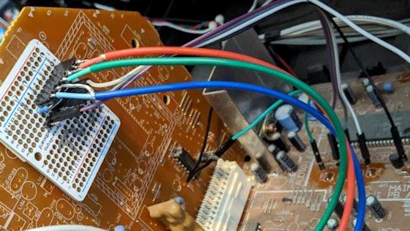
There was a time when all TVs came with only an antenna socket on their backs, and bringing any form of video input to them meant dicing with live-chassis power supplies. Then sets with switch-mode supplies made delving into a CRT TV much safer, and we could bodge in composite video and even RGB sockets by tapping into their circuitry. For Europeans the arrival of the SCART socket gave us ready-made connectivity, but in the rest of the world there was still a need to break out the soldering iron for an RGB input. [Jacques Gagnon] is in Canada, and has treated us to a bit of old-school TV input hacking as he put an RGB socket on his JVC CRT set.
Earlier hacks had inventive incursions into discrete analogue circuitry, but on later sets such as this one the trick was to take advantage of the on-screen-display features. The signal processing chip would usually have an RGB input with a blanking input to turn of the picture during the OSD chip’s output. These could be readily hijacked to provide an RGB input, and this is the course taken here. We see a VGA socket on the rear panel going to a resistor network on a piece of protoboard stuck in a vacant space on the PCB, from which a set of lines then go to the signal processing chip. The result is a CRT gaming monitor for retro consoles, of the highest quality.
For those of us who cut our teeth on CRT TVs it’s always good to see a bit of TV hacking. It’s a mod we’ve seen before, too.


Nice! Always good to see an old boob tube preserved and loved.
I came here to see how to modify a monochrome CRT to display color, and I have to say I was a bit… disappointed when I discovered that “CRT” vs. “CRT TV” is apparently the new “transistor” vs. “transistor radio”.
Come on. Virtually all CRT tv sets tossed in the last ten or twenty years were color. So even aside from nitpicking, there’s no lack of color sets if you want/need that. But they mostly lack video input.
Color wheels were obsolete when ntsc came along.
My ~15 year old 5″ black and white TV with video input, and all DLP based TV’s and projectors disagree with your remarks.
But you have to toss it out to prove him wrong :-p
He will find a Color CRT anywere in the garbage now…
Well, theoretically, you could do a https://hackaday.com/2019/10/01/monochrome-crt-and-liquid-crystal-shutter-team-up-for-color-video/
If you still decide to toss it, toss it in in my front yard :P
For retrocomputing, it’s probably easier to do this than find a CGA monitor.
BTW delving into a “headrest LCD” for in car DVD player, I found RGB pins called out on one of the internal connectors. Will take that further sometime.
Most TVs you get the RGB coming up to the neck board, but unless there’s much semiconductors on it, you can bet they are electron gun drive levels not 1V. Anyway you could look into your own single transistor amps to inject there if the rest of the boards are an incomprehensible mess.
after the demodulator you always have separate RGB at usable levels, the trick is isolation(older tvs had live chassis) and getting the sync in.
Once fried a few VGA ISA cards because the tv I was hacking had a wonky grounding setup, worked fine until I turned it off while connected to the computer, the vga was fried instantly.
Reading here it sounds like doing this to the older, pre-menu sets was really hard but in my experience it was anything but.
As a kid I bought an old tv at a garage sale. I’m guessing it was from the late 70s. It was color but from a time when that was still something to advertise. Anyway, I wanted to connect a VCR and a game system. The VCR had an RF modulator of course but the video quality was always better using composite.
So I cracked open the case. Inside I found that the VHF and UHF tuners were separate modules mounted in their own shielded boxes that hung from the face of the TV by their dials. The UHF tuner was not connected to the main board, it was connected to the VHF tuner. That made sense since one chose UHF by turning the VHF knob to ‘U’. It just fed through. The VHF tuner had a few solder posts on the back with wires soldered on leading down to the main board. It also had a plain old RCA jack with a coax jumper plugged in also leading down to the mainboard.
I guessed that the RCA connection was video. And I was right! I just unplugged it, soldered up an extension cable with a female RCA socket and ran that out the back through a vent hole. That’s all it took to get video. I didn’t even solder anything to the TV. I could just pull out my extension, plug the tuner back in and it would be like nothing happened.
I imagine audio must have been on one of those soldered wires. It wouldn’t have been too hard to find it. I was using an external amp and speakers wired into the vcr for sound so it wasn’t necessary. I just kept the volume turned all the way down and used it as a monitor.
Was the shield of that connector hot? Had I plugged the VCR and TV into separate outlets that turned out to be on opposite phases would I have had a fire? I don’t know. Who does that?
That makes no sense.
Tuners had radio output, just lower than tv frequencies. The signal still had to be amp!ified, and detected.
Even if it worked by some odd chance, it wasn’t RGB.
Dependent on the degree of integration I would think. I have come across modules in VCRs that went from UHF to video, haven’t found one like that in a TV but don’t get inside that many TVs personally.
Yes no maybe
Yes there is another IF stage after the tuner.
If the signal level injected is higher than the original signal level then it may pass though the attenuation from the next IF that will be cause by baseband or composite frequencies being much lower than normal.
After that there will be AGC that will bring the signal level back up to what is expected and at that point it is the correct frequencies. And in color.
The filter specs in old sets were poor and not strongly selective.
So I can see that this may work on some TVs but not others.
It’s not the right way to do this, it’s s real kludge or hack but I can see it working in an unintended way.
Huh. Well.. maybe that is how it worked. That is an interesting thought. I’m pretty surprised though because as I remember it the picture quality was just as good as anything I had ever seen by plugging into an actual factory-provided composite input.
So, no actual RGB then?
No, I suppose not. Sorry, I wasn’t thinking about that, I was only thinking about getting a baseband input. I suppose the author was right, you would need to get down to the high voltage stuff to get actual separate R, G and B inputs on one of those old sets.
I never worried about that back then because the accessories I had to connect to it, an Atari, a ColecoVision and a lower end VCR never had separate R, G and B outputs either. I suppose there’s a hack for that.. But it would have been beyond me in those days.
Still, I can’t imagine that old CRT could have produced any better of a picture if it did have an RGB input. That composite input looked really nice! I guess that was more my point. You could get a high quality input w/o going so deep.
These were great CRTs, my family had the 32″ D-series version after a 27″ version of almost exactly the one in the linked article was moved downstairs to upgrade an ancient Hitachi with no AV inputs.
The D-series had an incredible picture on component video for watching DVDs… once you found how to open the service menu and disable the NTSC “red boost” or whatever it was called.
Hitachi did their own thing with AV for a while, had a 9 pin din with RGB and sync I think, inputs. On models that didn’t have it exposed, there was often the unfilled solder pads on the edge of the board and the blank space on the back cover for it.
Oof, Sony WEGAs had that red boost BS. In NTSC regions (or perhaps just USA…?) it was called “AXNT” in the service menu and is best left at zero. And, oh yeah… “__NT”! I think it was “AXPL” in PAL regions :)
The Heathkit GR-2000 “Solid State” TV was great for hacking. I had three of them (or parts thereof). With the complete schematic and theory of operation, right down to the internals of each IC, you could have lots of fun. I put a switch on the video input so we could pipe an Apple ][c into it.
In Europe, TV manufacturers often included the venerable TDA3561 chip in its output stages for Teletext. Great little chip that accepted RGB 0.7v p-p signals, fast blanking and slow blanking signals so you could overlay text on TV pictures. I used that interface on a Grundig TV (much to the then wife’s displeasure) to act as a colour text / chunky graphics monitor for a 6809-based system I was building. The TDA3561 appeared before SCART, so TVs had an internal connector for a Teletext option. Fortunately they were isolated with a transformer, so safe to stick the computer straight in.
Maybe this is not the rifht forum but does anybody know how to convert old arcade monitor to lcd. Our church runs a outreach skating rinl and one of the monitors on our arcade game went bad and I purchased a converter card but I’m having a hard time gwtting it to work.
Any help is greatly appreciated. THANKS.
You can buy multi converters on eBay. They have a mix of rgb VGA and component video.
The one you want will have three pots on the PCB to adjust the r g and b signal levels as arcade units have higher signal levels than standard monitors.
The other issue is that arcade machines have one composite sync signal and LCD monitors require separate horizontal and vertical sync signals.
I think I have the right board but how do I add a picture to show you how I have it wired.
Sorry, new to forums. Also I think I have 2 sync wires, do I put them together?
Red,blue,green,black,white and yellow these are the wires I have after I removed the crt. Was there something else I should have kept from the old crt?
Thanks.
Hack a Day no longer allows embedded images to you have to post a pic somewhere else and link to it.
The game is obviously not JEMMA if you have two sync wires. JEMMA has only one SYNC wire.
Arcade games are well documented now so there will be a schematic available.
You can’t simply connect VSYNC and HSYNC wires together.
If you can tell me the name of the game and the model of the converter (or a link to where you bought it) then I can give you the exact wiring details.
The colors would most likely be …
Red – Red signal
Green – Green signal
Blue – Blue signal
Black – Ground … needs to be verified with a multi-meter.
The remaining two would either be VSYNC and HSYNC (in some order)
OR
White – combined Sync
Yellow – power … so you don’t want to blow things up with connecting the yellow without being sure what it is.
The arcade game is Mouse Attack and below is the link to the board.
https://www.ebay.com/itm/402326391874
Thanks.
The original connector that went to the old CRT could have just plugged into the converter board on the connector that has widely spaced pins (P3).
Not to worry, you can used the connector and wires that came with the converter.
Mouse Attack is super rare so I can’t get a full schematic. It is however a JAMMA standard board so I can tell you pin numbers and you can trace the wires.
Below is a list.
On the right hand side is the pin number on the JAMMA connector that the game board plugs into. You can google “JAMMA pinout” if they’re not marked on your JAMMA connector.
On the left is the colors (in order) of the wires that came with the converter board and have a plug that plugs into P11 on the converter board.
Red – red – JAMMA (12)
Green – green – JAMMA (N)
Blue – blue – JAMMA (13)
Grey – HSYNC (or combined sync) – JAMMA (P)
empty
Yellow – VSYNC – Don’t connect
empty
Black – Ground – JAMMA (14)
Thanks, when I get back to it I’ll try this.
Someone mentioned I might have to adjust the pot switches to see the game. What is the proper way to do this if I have to.
To adjust the pots …
Connect the screen to another video source – like a laptop or computer. Adjust the screen settings for contrast and brightness to 50% and take not of the brightness.
Connect the game through the converter to the screen. Adjust the three pots (at equal settings) so you have the same brightness as with the other video source.
Adjust the screen contrast and brightness to a comfortable setting.
If the colors don’t look right (they should) then you can tweak the pots to adjust the color.