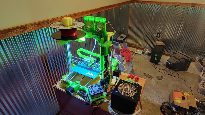
There was a time when the curious hardware hacker had to build their own 3D printer, because commercial models were so expensive as to be unaffordable except by well-funded institutions. We’re fortunate then to live in an era in which a good quality off-the-shelf machine can be had without breaking the bank, but that is not to say that home-made 3D printers are a thing of the past. Instead the community of rapid prototyping experimenters continue to push the boundaries of the art, and from that we all benefit. An example comes from [Morgan Lowe], whose 3DLS lead screw driven 3D printer joins the freely downloadable designs to be found on Thingiverse.
If at first sight you think it looks a little familiar, you are correct, as it takes its frame design from the popular AM8 metal frame upgrade for the Anet A8 off-the-shelf printer. It draws heavily from other A8 upgrades, and brings in some parts such as the extruder and bed from the Creality Ender3. This is the beauty of incremental open source, and the result is a belt-free printer that does a decent-looking Benchy on the bench, and as a party piece manages to print a slightly more hairy little plastic boat when suspended at 45 degrees by a rope from the ceiling.
When dipping a toe into the world of home made 3D printers it’s interesting to take a look into some of the earlier Hackaday RepRap posts, and see how far we’ve come.


This is interesting. I was under the impression, perhaps incorrect that the tooth belt systems had less backlash. The systems that use leadscrews for the Z axis get by with them because the Z axis in general only goes upwards. The X and Y axes are all over the place in a typical print. I also suspect the leadscrews cost more. Still a neat project.
If you look into the build, he uses anti-backlash lead nuts, which contain a lead nut with a follower nut coupled by a (hopefully pretty stiff) compression spring. This forces the two nuts away from each other which preloads the nut in one direction and thus removes the backlash in theory. In practice I don’t know how these compare to belts.
Belts may have less backlash, but they are springy.
Leadscrews with anti-backlash nuts have absolutely no backlash. I have designed machinery for over 20 years with belts, ball screws and lead screws. There’s a place for each, but nothing changes the fact that ballscrews and leadscrews are the most precise and accurate way of transforming rotary into linear motion. You cannot design a $200.00 printer with a belt system without backlash, in fact, you can multiply that amount 10 fold and still not have a 0 backlash belt system. Doesn’t matter how tight the belts are, because ultimately, backlash has nothing to do with that – it is due to the designed in riding clearances between pulleys and belts. I have actually engineered and manufactured such systems having to take into account the intrinsic back lash of the belt systems.Not only that, the small, 2mm pitch toothed pulleys and belts used in 3D printers do not transfer motion linearly. There’s a minute change in the effective radius of the belt leaving an entering the pulley that inadvertently affects linearity, causes the belt to ring, and in turn introduces vibration into the system. The effects of such vibration can be seen on the finished parts of even the better belted printers in the market. Belt systems are cheap and for most people, good enough, but better they are not.
Leadscrews with anti-backlash nuts can ABSOLUTELY have backlash.
There are two types of anti-backlash nut: spring-type and screw-type. The screw-type ones are guaranteed to permit some backlash unless they’re cranked up so tight that they stretch the leadscrew; this doesn’t permit any lubrication, so they wear very quickly. The spring-type ones can still permit backlash if they’re loaded heavily enough to overcome spring tension.
If you assert that “Leadscrews with anti-backlash nuts have absolutely no backlash.”, then I have to call into question the credibility of your “I have actually engineered”; any actual engineer knows better than that.
Resize the bearings in the nut and mechanically remove the backlash. Ive built many cnc’s and they have no noticable backlash when assembled properly. Spring nuts are a bandaid.
Oh nonono…belts, especially GT2 belts are awful compared to leadscrews. GT2 belts at real printing speeds have all kinds of backlash, and that’s if the user knows how to properly tension the belt. Most printers don’t have properly tensioned belts, nearly skipping teeth the whole time and these are usually the folks claiming they need a 32-bit uP for a zillion microsteps for microns of accuracy. With your printer off, hold your pulley and push your print head and you’ll see 1/8″ slop in most GT2 setups.
This is one reason I made this machine, the other was because I had challenged myself to make a whole printer a year ago then I started modding mine with lead screws and a few people made comments on how impossible it was.
Challenge accepted.
Now the 3DLS is my daily driver. It’s been printing every day for 3 months now and has been flawless.
Challenge won.
Heh. People can’t reconcile that a belt is a vibrating, singing affair with so much oscillation even WHEN you get it the right tension with the right belt materials. It’s like a violin or guitar string folks. Heck, people tell you to pick a certain tone for tension when plucked even. (Hint: What does Creality use for their Z axis? It has less backlash than the belt and it’s just that it’s cheaper to use the X/Y belts. All about costs and what they think they can get away with to shave pennies off of their BOM)
It’s simpler/easier/cheaper was all that you had there with the GT2s, etc.
Well done on the 3DLS and the LSD printers. It’s now in the plans to duplicate your work- thanks for sharing. I have suspected for some time that it’s not so much that it was “undoable”- it’s a situation of people “knowing” and not really knowing/understanding the whole thing in the first place.
Just think about it. All CNC mills use a form of screw be it a lead screw or ball screw.
And they are all more accurate then a 3D Printer down to 0.001 millimeter .
I built my own and get less then 0.01 mm tolerance out of it , you just cant get that out of belts
Also you “ringing” isn’t really an with screws.
Everyone seems to keep going on and on about backlash…and that it’s “a problem” with the lead or ball screws. Also something of speed.
Reality is that a belt sings. It’s a string, people. You can’t get precisions or tolerances like this with that sort of stuff. The vibration and backlash (Yes, you actually have it with the belts and that damping effect from the rubber to keep it from singing too much is…heh…backlash…) washes out many of the gains that is believed to be there with the GT2s and other timing belts.
The reality is that a GT2 is *cheaper* than the other…but not by enough these days to not give it serious consideration if you’re doing your own build. It’s a mass production consideration and for some designs and products, it’s moot. You run with the screws.
Also I thought leadscrews were a lot slower. I can see them for having to move large heavy heads (like a CNC cutter) but it doesn’t seem like a proper application here.
They are using 2mm 4-start leadscrews, so 8mm travel per revolution. So, 40% the speed of a typical 10-tooth GT2 pulley (20 mm / rev). Still quick. Easily capable of 50 mm/s, maybe 100 mm/s with a good driver.
I would be more worried about wearing out the nuts, since they aren’t using ballscrews.
well, I *may or may not* have used Tr8x2 4 start leadscrews on my z axis with printed nuts…
I made them out of PETg (which I later on realized is rather too grippy for this stuff) and they worked perfectly, didn’t get any wear after 6 months, and the printer was able to do 85 mm/s with TMC2130’s running at 36V. So, I guess it wouldn’t be that bad. They had zero backlash too
Me too… but they have this video https://www.youtube.com/watch?v=TQ1KrQZN0Y0
I built a printer using Openbuilds C-Beams a while back (still using it now), and I can print at 100mm/s on a Duet wifi without issue. The biggest issue I found is the noise and maintenance. It’s not quiet, even with Trinamic drivers. Maintenance wise, I think it has more to do with the Openbuilds parts than anything else.
On the plus side, there’s no backlash and no ringing/ghosting.
So far about 6 months into it’s life everything is still tight and running smooth. I used SuperLube silicone grease on the screws and am running brass ant-backlash nuts. They are 4 start M8 leadscrews with closed loop stepper drivers easily capable of the high RPM needed. I have travel at 150mm/sec and print at 100mm/sec with great results.
Belts are like rubber bands, no matter what. It’s the nature of them. They are fine for a printer, this was built because I could. I am in the process of making a second one now.
A agree – anti-backlash nuts can work very well in this situation. The brass nuts should be replaceable and outlast the steel screws multiple times over but the anti-backlash design helps extend the life even more.
So I’m in – have some of this around the shop (actually have a spare SKR 1.4 Turbo), a lot of the rest of the mechanicals that I don’t have around ordered, and other stuff printing as we speak. Looks like a really interesting build.
Awesome! I got 9 full bed prints to do and parts coming from China for my second one now. If you can post a make of yours over on thingiverse please! I’ll also be happy to help there if you have any questions.
On mine I custom made every cable since I had the tools to do that laying around. This is not required, there’s included wire management too.
> print at 100mm/sec
Obviously, you are not printing at 100mm/sec. You may have set that in the slicer, but the printer never reaches that speed. People have been making false claims like this since forever.
Agreed. Its more useful to post the acceleration you’re using than the max velocity.
Look at the thingiverse link, in my firmware which I setup for it and on youtube.
It’s accel is set to 300, which is kinda low. It will go much higher but I just haven’t. Max speed is also set to 300.
https://www.youtube.com/watch?v=TQ1KrQZN0Y0
120mm/sec print there.
Remember kids, this is 24V with closed loop stepper control on X and Y. It’s going to move. I’ll set the accel to 3000 and run a print at 150mm/sec here in a minute. Youtube video will be posted
Morgan,
What do you use for thrust washers on those leadscrews, and where are they, and how do you preload them? It’s not obvious from the video, except that there isn’t one on the Y axis motor end.
It thrusts up against the bearings. In the prints is a small collar and then it uses a stop collar with set screw. Pre-load is just by hand. So long as it’s not loose. This has held up as the bearings are still the very first set from the first experimental build.
Because the Y has to pass over the frame it thrusts against the front bearing support while the X is all in the motor side.
Here’s the video of the 150mm/sec print starting, the screenshots and details of the slicer and marlin config are in the description. I had to restart it to change out the bad fan but it’s going now and the timelapse and result will be posted to Youtube as well.
https://youtu.be/QUFZcTm5FsU
I’ve got a big standard i3 clone and if I run it at 120 mm/s it flies and the print quality is great. Doing a big print now with lots of long straight runs and any fool could see it’s hitting the 100 mm/s it’s set on.
I’ve been sort of designing one to be like the Ultimaker, but I’ve been torn between that and another design using two Y steppers to move a gantry that has the X motor.
Of course using linear rails, instead of the rods or wheels on v-rails.
Why linear rails instead of rods? What advantage do the rails have over the rods with ball bearing slides?
1. They are a easier to mount to 20 and 30 profile.
2. There are well known companies that make high quality rails.
4. Rails look cooler.
There are some other alternatives.
Not to mention that the rods are harder to make precisely than the linear rails.
I honestly don’t get why people have a thing for the rods over the other.
Looks cool/familiar doesn’t cut it over performance. Performance wins EVERY time and many’s notions of what “works” and doesn’t actually aren’t in connection with reality- they’re using what they were told by someone else who didn’t know any more than they did there.
This being said about the rods- if you can get clean, straight linear rods, you run with what you lay your hands ON. If that’s what the design calls for and I can get them, you can bet I’ll be doing that. If I can’t, then the re-design begins for the other that I can lay hands on.
> This is the beauty of incremental open source,
This is not an Open Source design, since it does not have an Open Source license.
Per the license on Thingiverse it is Creative Commons – Attribution – Non-Commercial licensed.
This was designed in Solidworks 2019. The Solidworks files are not posted however it is free to modify. I can prove IGES or STEP files for it as well.
Considering that people don’t seem to have clues here… You probably ought to put those on the Thingiverse thing there or provide a GitHub/etc. repo for the content.
They’re going to come up with all sorts of reasons to tear you down…guess it’s time to put paid to all of that. What do you call the STL files, folks? Didn’t anyone ever do mods/remixes off of just those alone or use them as a crib sheet for a new design (Hell, I know I have…)- so it’s source, people…just to be able to print it.