There’s kind of a special joy in making instruments, no matter how simple or complex they are. Even if it’s a straight-up noisemaker, that’s noise you can be proud of. And besides, noise plus rhythm equals music.
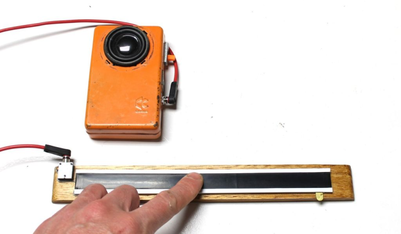
Whenever you’re ready to have some next-level fun, try making controllers for your DIY instruments. Synthesizers of all stripes are often controlled with various types of potentiometers. While it would definitely be an interesting exercise to make your own standard twist-style potentiometer, [lonesoulsurfer] shows that making a ribbon controller is relatively easy.
 A ribbon controller is essentially a deconstructed potentiometer that uses your finger to actuate the wiper. Here the wiper is made from Velostat, a fun, low-cost conductive material that’s also pressure-sensitive. The rest of the ribbon controller is a sandwich of thin copper plates and non-conductive plastic mounted on a wood base.
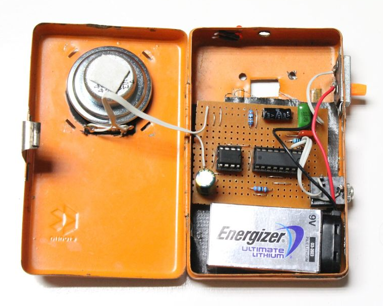
But what’s a fun controller without a fun instrument to control? As a special bonus, [lonesoulsurfer] made a little square wave-squirting synth based on the 4046 hex inverter and included the schematic for it. Slide your finger past the break to check ’em both out.
Depending on what you have lying around, it may be easier to make analog instruments like this rubber band boinger or its country cousin, the wheelbarrow bass.


I did work on ribbon controller using a Kanthal D tape, two-sided tape and aluminum foil. It was going to work like in Trautonium, but with small constant current source and op-amp for voltage sensing to control a simple square wave synth that used one of those small DIP-8 PIC micros. Ribbon part actually worked, but capacitive voltage multiplier and inverter for op-amp was underpowered. I’ll work on that some day…
The difficulty is that when you touch the ribbon, you get a rather strong AC hum from your fingers and it tends to mess up with any voltage measurement. If the whole thing runs on batteries, it doesn’t matter, but as soon as you plug into an amp your oscillator goes bonkers because the ground lead gives you a path for all the currents that you are picking up from the environment, or maybe there’s some voltages in the ground wire and you’re conducting them to the floor or something. Either way, the point where you touch the ribbon becomes a path for these currents and it sums up to the currents that go through the ribbon.
The solution to that problem is to 1) insulate the ribbon from the top. This still gives a capacitance path through the insulation so you still get a tiny bit of modulation and hum, or 2) invert the whole thing and put a grounded metal ribbon on top – preferably still insulated on the top side.
Option 1 gives you a simpler way to read the strip as a resistor divider but it doesn’t completely remove the issue. Option 2 is more difficult to measure, but it gets rid of the hum entirely. Number 2 is also better because the metal strip holds up to playing a lot better than the plastic, and you can tension it so it gives you a well defined contact point.
Actually it’s true if the entire synth is analog or you are not processing your ADC data in any way. And depends on the SNR of the entire thing. I just oversampled the ADC result which averages any LSB noise and then shifted it to loose more LSBs. Additionally in case of too much interference one could add some low-pass filtering either in hardware or in software. Dropping the sampling rate would also do the trick. Also by playing with the averaging/oversampling routine and sample rates one could achieve nice portamento…
Originally I was going to use Kanthal D wire as a top over the aluminum “wiper” strip, but Kanthal D makes very poor strings…
That depends on how strong the error is. Mine was just saturating the buffer amplifier to the ADC and banging it from rail to rail.
Point being, you may have 100 volts AC from eg. an ungrounded ATX power supply buzzing at the tip of your finger, and even though your impedance is something like 1 MOhm, the resistance of the strip is about 50-100 kOhm, so the division makes 5-10 Volts AC appear at the input of the buffer amp.
If you’re lucky, you’ll never encounter the effect – but the moment you get a ground loop going, it’s going to play havoc.
The venerable PAiA Gnome microsynth (I built one in 1976 while bombing out of uni) had a conductive plastic ribbon controller, but it had a probe that you held and touched/pressed to the ribbon.
I’ll just leave this here
https://www.youtube.com/watch?v=tf5k6ndcNPY
Interesting.
Huh. I was just looking for viable, somewhat high-ish resistance tapes/films earlier today. I’ll have to keep velostat and some of the other antistatic bag materials in mind.
http://www.oocities.org/tpe123/folkurban/synthstick/synthstick.html
That’s one that’s intrigued me for a *very* long time… mind you, *any* attempt by me at any sort of musicality ends rapidly in severe auditory pain to any bystanders within earshot… you’ve heard the phrase, “couldn’t carry a tune in a bucket”…? LOL. You could bring me a BelAZ 75710 (the absolute largest AFAIK of the “haul truck” vehicles, those special extra-huge dump trucks for massive coal mining operations)… heck, you could bring me a frigging fleet of them, it wouldn’t matter, I still couldn’t carry a tune in ’em all. I’m *that* awful. I should probably be legally barred from anything more musically sophisticated than whistling along with the radio (which, ironically, I used to be pretty dang good at for some weird reason).
But I enjoy designing and building electronic musical instruments. Can’t play them to save my life — it’d invariably come out like a particularly drunken (and out-of-tune) Garfield on a back-alley fence — but, hey, maybe I could make them for someone else?
The funniest part of all of this is that I almost can’t not *listen* to music.
I’m just about the same. It’s like making fancy footballs but a terrible player on the field. Don’t let that stop you. Assuming you get musical ideas… just try them out. Use digital recording and editing to build up what you’re imagining. As each obstacle or challenge appears, work through it, or around it. It should be fun, and you learn stuff.
Basically, build something and explore the heck out of it. Try to find all the possible sounds/noises/patterns. Try it in combination with other stuff. Record anything interesting.
Use headphones til you have something to show off ;-)
Umm – I’m pretty sure that a hex inverter is 4049, not 4046.
The 4049 is a hex inverter, but I can imagine someone using the VCO from the 4046 PLL.
So either the number is wrong, or the surrounding words are wrong.