
Here at Hackaday, we love a good clock project. And if it’s an artistically executed freeform sculpture, even better. But tell us that it’s also a new spin on a classic project from two decades ago, and we’re over the moon for it. Case in point: [Paul Gallagher’s] beautiful recreation of an LED clock riffing on one originally made as a weekend project in early 2000.
Wait, wait. Hold up.
*Ted unclips the microphone from his lapel and stands up from his chair*
OK, dear reader, if you’ll allow me, we’re going to do this one a little differently. Normally I’m supposed to write in the voice of Hackaday, but this project has personal meaning for me, so I’d like to break the rules a bit. You see, the original clock project was mine — one I did over a weekend a long time ago, as evidenced by the “2/13/2000” date on the PCB — and I was quite honored that [Paul] would choose my project as inspiration.
When, on the 20th anniversary of creating this clock, I posted a Twitter thread to commemorate the event, [Paul] picked up the ball and ran with it. You can see the original Twitter thread here. Pictures of the home-etched single-sided board were all he needed to reverse-engineer the relatively simple design, and then re-create it with style.
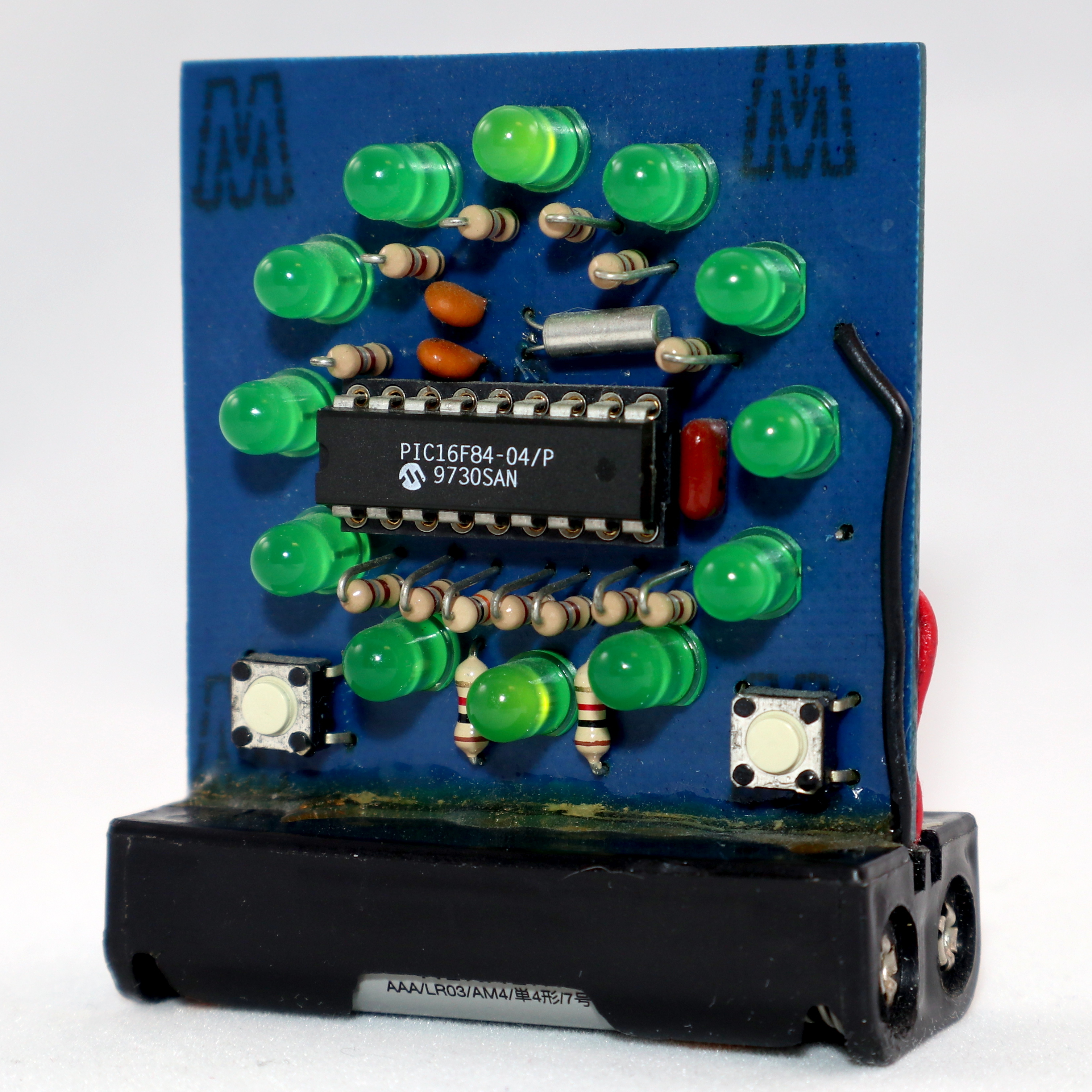
The design uses a PIC16F84 microcontroller. This was one of the first microcontrollers to really become popular with hobbyists, the key features being the serial programming algorithm which allowed easy homebrew programmers, and the FLASH memory. If I recall correctly, my original programmer ran off a PC’s parallel port. I probably have it in a box somewhere. Each of the 12 LEDs is driven through a separate resistor from individual GPIO lines, while a 32.768 kHz crystal serves as the timebase. Finally, two buttons allow you to set the hours and minutes.
How do you represent three separate hands on such a display? In this case, each hand blinks at a different rate. The hour LED is solid, and the second LED blinks faster than the minute one. You can check it out in [Paul’s] video after the break, and admire the beautiful simplicity of his layout.
Since he was able to re-create the circuit exactly, [Paul] was able to drop-in the original assembly code that runs the clock. True-to-form, Microchip still manufactures the PIC16F84, and their latest tools have no problem with such legacy code — it just works.
Even though our circuit-sculpture contest is over, Hackaday is always on the lookout for interesting free-form creations like this one, so if you’ve made one, or just spotted one in the wild, drop us a line.
[Thanks Emily]


My question is, even though II can see the seconds, minutes, and hours indications flashing at a different rate, how can you tell if it’s a given hour, and it’s anywhere between the hour and up to about 5 minutes after?
when i thought about it, i wanted interpolation, so it would alternately blink two LEDs at a rate dependent on which LED was closer to the real value. don’t know if that would really be easy to interpret as a user but it struck my fancy. :)
anyways a 5 minute clock is good enough for most people. i wouldn’t bother with a 5 second hand on a 5 minute clock though..
Time is money
When doing an assessment on whether or not to diy, one factor is the most important. Does the off the shelf solution satisfy my specific needs? Can I customize it to satisfy those needs? If not then I’m rolling my own.
Beautiful!
Neat looking project, though the blinking would drive me bat shit crazy. What would be cool and very simple and zen would be for it to have LED’s that are on all the time but fade proportionally between the “hours” 12:00 would be the top LED on full brightness, 12:05 say, the 12 would be quite bright, but the one would be fading on a bit. 12:15 more so, 12:30 they would be about the same. 12:35 the one would be a bit brighter than the 12.. All the way up to 1:00 where the one would be full on and the cycle repeats.
Now, if you have enough pins to play with any of the multicolored LED’s either raw or the addressable ones, you could do the other hands in other colors on the same LED’s. That may be soothing to look at.
This is definitely a very cool idea, but as I said, the flashing would drive me nuts in short order.
Cool clock. I never did one of those.
It was definitely the FLASH that made these popular.
The predecessor 16c84 was one time programmable so the first step to debugging code was to throw (another) chip in the bin.
The Harvard architecture / RISC / fixed depth dedicated PC-Stack made it interesting to code for in asm.
These PIC chip became the Arduino of the day with PIC-BASIC.
I remember an emulator that ran on a PC with witch you could see your code run at a hardware level.
And yes, back in that day you could run anything though a parallel port. Micro controller programmers, EPROM programmers, stepper motors or whatever.
Until Windows XP you had direct access to the parallel port from an application level right though the OS. It was a hardware hackers dream because you had precise control over signal timing.
You could even directly access the parallel port from coding platforms like GW BASIC, Q BASIC or Quick BASIC so you didn’t need to know anything about x86 asm to get your hardware working.
Direct access to the parallel port does not mean you get accurate timing. Preemptive multitasking since early 90es on windows means you cant really predict delays properly, so without any specialized driver you’ll be lucky to get accuracy within tens of milliseconds (true to this day).
If it mattered to you though, you could mess around with the minimum timeslice (Think it was in win.ini could be wrong) and change task priorities until it worked good enough for you.
It’s all about the context of the time.
The first PCs had a SPP mode for LPT ports. At that time UARTs maxed out at 9600 BAUD. The LPT port was much faster.
A common software package (LapLink) for transferring files between PCs used the LPT port so did may ZIP drives and early CD ROMs.
Early PCs had a CPU clock if about 3.7MHz, dog slow but remember that this was close to state if the art computing so anything that you wanted to connect to the LPT port was probably slower anyway.