Reverse Engineering Saves Trashed LED Panels

While out riding his bike, [Hammond Pearce] came across a dumpster overflowing with large LED panels. Despite the fact that the model numbers didn’t reveal anything helpful after some online searching, he decided to pedal off with as many as he could safely carry. The COVID-19 lockdown left him with only a limited set of tools, be he still managed to crack the protocol used to control his e-waste score and document it for our reading pleasure.

Between the helpful labels on the PCB silkscreen and the advice of a friend that used to work on digital road signs, it didn’t take [Hammond] long to get a general idea of what the panels were looking for in terms of power and control. Especially once he noticed the MBI5024 shift registers dotting the board.

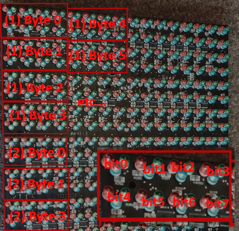
The next step was to take an ATmega328PB based development board and start throwing data at the panel’s input lines to see if he could elicit a response. With careful attention and some custom code, he eventually figured out that each byte of data sent down the line would control a 4 x 2 section of LEDs.

Once he had the basics down, the next step was to start expanding his code to handle things like shapes, text, and daisy-chained panels. After posting some of his work to Reddit, cyber-sleuths determined that the protocol appeared to be some variation of HUB75, which gave [Hammond] hints on what some of the other pins in the connector might be used for. He’s released all of his code online for anyone who might find it useful, but since he still doesn’t know who made these panels and why there’s really no telling how many of them are actually floating around out there.

Figuring out how to talk to an unknown or undocumented piece of hardware can be intimidating, but success stories like these are reminders of why it’s worth putting the effort in. As we’ve seen, the difference between trash and treasure is often a keen eye and a few lines of code.

Nightmare Fuel Telepresence ‘Bot May Become Your Last Friend

After this pandemic thing is all said and done, historians will look back on this period from many different perspectives. The one we’re most interested in of course will concern the creativity that flourished in the petri dish of anxiety, stress, and boredom that have come as unwanted side dishes to stay-at-home orders.

[Hunter Irving] and his brother were really missing their friends, so they held a very exclusive hackathon and built a terrifying telepresence robot that looks like a mash-up of Wilson from Castaway and that swirly-cheeked tricycle-riding thing from the Saw movies. Oh, and to make things even worse, it’s made of glow-in-the-dark PLA.

Now when they video chat with friends, TELEBOT is there to make it feel as though that person is in the room with them. The Arduino Uno behind its servo-manipulated vintage doll eyes uses the friend’s voice input to control the wind-up teeth based on their volume levels. As you might imagine, their friends had some uncanny valley issues with TELEBOT, so they printed a set of tiny hats that actually do kind of make it all better. Check out the build/demo video after the break if you think you can handle it.

Not creepy enough for you? Try building your own eyes from the ground up.

Continue reading “Nightmare Fuel Telepresence ‘Bot May Become Your Last Friend”

Halloween Costume Turned Positive Pressure Suit

As a general rule, you probably shouldn’t be getting your Personal Protective Equipment (PPE) from the party store. But these are exceptional times, and rather than potentially depriving medical professionals the equipment they so desperately need on the front lines, the team at [Robots Everywhere] has been looking into improvised PPE. We’re not sure things are at the point where you would need to don this DIY Positive Pressure Suit (PAPR), but it’s certainly an interesting look at what’s possible when you think outside the box.

At the most basic level, a PAPR is a mostly air-tight garment that is continuously pumped full of filtered air. As long as the pressure inside the suit is higher than outside, there’s no way airborne bacteria and viruses can get in without traveling through the filter first.

For this project, the folks at [Robots Everywhere] took an inflatable astronaut costume and replaced the dinky original air pump with a much larger 12 V unit designed for inflating air beds. Upgrading the pump not only increased the internal air pressure of the suit, but also made it easier to add a HEPA filter to the inlet. As long as the suit is inflated and there are no leaks in the hose, the wearer will be surrounded by a bubble of filtered air.

Presumably, you don’t want to be tethered to the wall though, so the write-up briefly touches on how the pump system can be made more mobile with the addition of an RC-style battery pack. With the pump and batteries secured in a pouch attached to the suit, the wearer is free to venture outside the confines of their self-isolation bunker and go about their dystopian daily business.

A getup like this might seem a bit excessive, but with so many folks desperate for information on homemade protective gear, we aren’t passing any judgment. The team says you can modify a cheap painter’s suit in much the same way, but frankly, that doesn’t sound nearly as fun to us.

[Thanks to Aron for the tip.]

Touch-Typing On Fingertips? Prototype Says It Could Work

The fingertips are covered in touch sensors, each intended to be tapped by the thumbtip of the same hand.

Touch-typing with thumbs on a mobile phone keyboard is a pretty familiar way to input text, and that is part of what led to BiTipText, a method of allowing bimanual text input using fingertips. The idea is to treat the first segments of the index fingers as halves of a tiny keyboard, whose small imaginary keys are tapped with the thumbs. The prototype shown here was created to see how well the concept could work.

The prototype hardware uses touch sensors that can detect tap position with a high degree of accuracy, but the software side is where the real magic happens. Instead of hardcoding a QWERTY layout and training people to use it, the team instead ran tests to understand users’ natural expectations of which keys should be on which finger, and how exactly they should be laid out. This data led to an optimized layout, and when combined with predictive features, test participants could achieve an average text entry speed of 23.4 words per minute.

Judging by the prototype hardware, it’s understandable if one thinks the idea of fingertip keyboards may be a bit ahead of its time. But considering the increasingly “always on, always with you” nature of personal technology, the goal of the project was more about investigating ways for users to provide input in fast and subtle ways. It seems that the idea has some merit in principle. The project’s paper can be viewed online, and the video demonstration is embedded below.

Continue reading “Touch-Typing On Fingertips? Prototype Says It Could Work”

An Op-Amp From The Ground Up

We are all used to the op-amp, as a little black box from which we can derive an astonishingly useful range of circuit functions. But of course within it lurks a transistor circuit on a chip, and understanding the operation of that circuit can give us insights into the op-amp itself. It’s a subject [IMSAI Guy] has tackled during the lockdown, recording a set of videos explaining a simple discrete-component op-amp.

The op-amp circuit in question.

He starts with the current source, a simple circuit of two diodes, a resistor, and a transistor that sets the bias for the two-transistor differential amplifier. This is followed by a look at the output driver, and we would expect that shortly to come will be a video on the output itself. Start the series with the first episode, which we’ve placed below the break.

His style is laid-back, making it a restful watch as he builds each circuit on a breadboard and explains its operation with the aid of a multimeter. If this whets your appetite for more on simple op-amps, we looked at the first integrated circuit op-amp back in 2018.

Continue reading “An Op-Amp From The Ground Up”

How Much Is DIY Worth To You?

It all started with an article about Wink Labs putting a monthly fee on their previously free service. It wasn’t so much the amount they were asking ($5 / month) that raised my hackles, but rather the fact that they would essentially render a device that you ostensibly bought worthless unless you paid up. I’ve ranted about this enough recently, and the quick summary is that IoT companies seem very bad at estimating their true costs, and the consumer ends up suffering for it.

So I started thinking about the price myself. Is $5 per month for a home automation service a lot or a little? On one hand, if you stretch that out to, say, 10 years, you end up with a net present value of something north of $400, plus $70 for the device. That’s a lot, right? Surely, I could DIY myself a solution for less? Or am I falling into the same IoT trap?

This isn’t hypothetical, because I already have a modest DIY home automation system. We run a bunch of switches, have temperature and humidity loggers in relevant rooms, and the washer and dryer notify us when they’re done. I also use the MQTT infrastructure for all sorts of fun projects, but that’s a bonus. Our hub is a $10 Orange Pi and a long-since depreciated WRT54g router, and it’s run for four years now, and probably will last another six. So that looks like $460 in my pocket.

On the other hand, it’s only really a bargain for me because I already knew what I was doing when I set the system up, and what I didn’t know I wanted to learn. Realistically, I probably spent around 20 hours on the system in total, but most of that has been adding in new devices and tweaking old ones. You’d have to do this sort of thing with any other system too, although my guess is that the professional systems are more streamlined at enrolling new gadgets: I have a whole directory full of Python scripts running as daemons and have to do a lot of hand editing. Still, assuming nothing else drastic happens to the system, I’m probably winning by DIYing here.

But imagine that I had little or no technical clue, and even flashing an image of a pre-configured home automation system to a Raspberry Pi were new. How much time does it take to learn how to do something like that? How much time to learn to administer even such a simple system on your home network? If it took the real me 20 hours, it could be easily twice that much for the hypothetical me. Let’s say 46 hours of time invested. $10 / hour is below minimum wage in many places, and this isn’t minimum wage labor, and that was fairly optimistic.

In the end, the $5 per month is probably pretty fair if the system works. Indeed, when I look around at all of the systems I’ve built, most all of them have taken more time to build than I thought when I was starting. Of course, I’ve enjoyed it most of the time, so maybe it’s not fair to apply my full consulting rates. (Which if I charged my father-in-law for tech support, I’d be rich!) But it’d probably be naive to say that everyone should just DIY themselves a home automation solution when the going gets tough.

So look around you and revel in the hours you’ve spent on your various DIY projects. Who knew that they were worth so much?

This article is part of the Hackaday.com newsletter, delivered every seven days for each of the last 200+ weeks. It also includes our favorite articles from the last seven days that you can see on the web version of the newsletter.

Want this type of article to hit your inbox every Friday morning? You should sign up!

Beautiful Free-Form LED Clock Recreates 20-Year-Old Weekend Project

Here at Hackaday, we love a good clock project. And if it’s an artistically executed freeform sculpture, even better. But tell us that it’s also a new spin on a classic project from two decades ago, and we’re over the moon for it. Case in point: [Paul Gallagher’s] beautiful recreation of an LED clock riffing on one originally made as a weekend project in early 2000.

Wait, wait. Hold up.

*Ted unclips the microphone from his lapel and stands up from his chair*

OK, dear reader, if you’ll allow me, we’re going to do this one a little differently. Normally I’m supposed to write in the voice of Hackaday, but this project has personal meaning for me, so I’d like to break the rules a bit. You see, the original clock project was mine — one I did over a weekend a long time ago, as evidenced by the “2/13/2000” date on the PCB — and I was quite honored that [Paul] would choose my project as inspiration.

Original Clock Project dated 2/13/2000

When, on the 20th anniversary of creating this clock, I posted a Twitter thread to commemorate the event, [Paul] picked up the ball and ran with it. You can see the original Twitter thread here. Pictures of the home-etched single-sided board were all he needed to reverse-engineer the relatively simple design, and then re-create it with style.

The design uses a PIC16F84 microcontroller. This was one of the first microcontrollers to really become popular with hobbyists, the key features being the serial programming algorithm which allowed easy homebrew programmers, and the FLASH memory. If I recall correctly, my original programmer ran off a PC’s parallel port. I probably have it in a box somewhere. Each of the 12 LEDs is driven through a separate resistor from individual GPIO lines, while a 32.768 kHz crystal serves as the timebase. Finally, two buttons allow you to set the hours and minutes.

How do you represent three separate hands on such a display? In this case, each hand blinks at a different rate. The hour LED is solid, and the second LED blinks faster than the minute one. You can check it out in [Paul’s] video after the break, and admire the beautiful simplicity of his layout.

Since he was able to re-create the circuit exactly, [Paul] was able to drop-in the original assembly code that runs the clock. True-to-form, Microchip still manufactures the PIC16F84, and their latest tools have no problem with such legacy code — it just works.

Continue reading “Beautiful Free-Form LED Clock Recreates 20-Year-Old Weekend Project”