There are many ways in which one’s youth can be misspent, most of which people wish they’d done when they get older and look back on their own relatively boring formative years. I misspent my youth pulling TV sets out of dumpsters and fixing them or using their parts in my projects. I recognise with hindsight that there might have been a few things I could have done with more street cred, but for me, it was broken TVs.
TV Pictures From More Than Just Down The Road
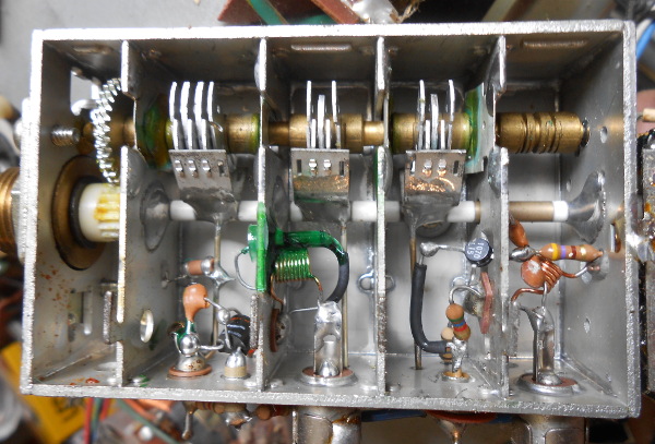
As a radio enthusiast at the time I would zero in on the RF side of the circuit. Here in the UK, that is a UHF tuner and a 36 MHz IF strip. I would tweak and modify them endlessly, making antenna amplifiers, UHF transmitters, 70 cm amateur TV gear, and memorably even a rudimentary spectrum analyser that would give a plot of the local TV transmitters on my oscilloscope screen.
In particular I was fascinated by DXTV, the idea that during a significant enough atmospheric “lift” I might snag stations from miles away, a distant part of the country perhaps, or even from Mainland Europe. In this I was largely unsuccessful beyond seeing a very snowy version of the local news in Norwich from time to time, but along the way I learned a huge amount about how radio works, and in particular about the effect of electrical noise on receiver performance.
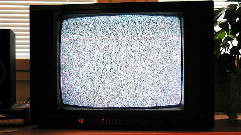
It’s easy to forget about noise when watching a modern digital TV, because if there is no TV channel on the screen there will always be something such as the program guide or other graphics there instead. When an analogue TV had no channel to display, it would instead show you whatever random noise its receiver could resolve, a “snow” on the screen accompanied by the whooshing sound of white noise on the speaker. If the set was tuned to a transmitter from way beyond its normal range then the noise level would be of a similar magnitude to that of the signal, and the picture and sound would be there but with visible snow and audible noise.
I soon learned that if I added an amplifier between my antenna and the TV I could get a stronger signal, but the results were disappointing. I was soon departing down the rabbit hole of better antenna amplifier design, tweaking cavity tuners to make tunable amplifiers, and seeing out the particularly prized at the time MOSFET tuners to donate their dual-gate BF981 transistors. Without realising it I was learning about noise and its effect on receiver performance, and a few years later when I was an electronic engineering student I would learn some of the theory and maths behind it.
The First Amplifier In The Chain Affects All That Follow
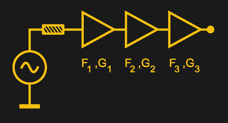
What I learned was the Friis noise equation, named for the Danish born engineer Harald Friis who worked for Bell Labs through much of the mid 20th century. It takes the noise factor, the ratio of output to input noise for a chain of amplifiers, and derives it from the individual noise factors and gains of each of its parts. What this does is teach the novice engineer about the effect of the gain in each stage in amplifying the noise from the previous stage as well as in adding its own noise to the pile. Thus the noise contributed by the first amplifier in the chain is amplified by all the others, and contributes most to the final result.
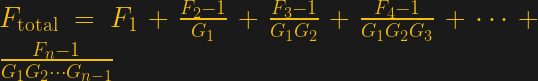
As can be seen from the formula, F1 is the noise figure of the first amplifier, and it is the only member of the progression that is not a fraction. Thus it has the most influence on the overall noise figure of the complete system, and here was where I discovered the value of the good quality preamp back in my DXTV days. As the first component my off-air signal encountered, its noise figure had the most effect on the performance of the rest of the system, and thus the most effect on that snow in my low-signal picture. My tunable cavity BF981 MOSFET preamp might have been annoying to use because it required retuning along with every channel shift of the TV, but its superior performance over the bipolar transistor in the TV tuner greatly reduced the system noise.
If your work lies in the realm of microcontrollers and digital circuits you may have less use for this equation than I did, but since it applies to many more situations than my teenage DXTV setup it is still a very useful thing to have some knowledge of. After all, every analogue system can be beset by noise!
Header image: Mysid / Public domain


Wow, you really got around then. Go Jenny! I also was lucky to be exposed to quite a lot of analog and RF before there was this digital thing, and it’s been very useful for a wide range of endeavors.
Noise is still a factor in digital, just like in FM – it’s just invisible below some threshold. But when it becomes an issue – you will do a lot better knowing the rules we learned in the analog world to address it! Ditto analog concepts like..transmission lines, reflections, and why there is ringing and overshoot – making digital transmission more sensitive to … noise (because signals add up in analog land and the combo might exceed an error threshold neither alone does).
Knowing more about noise is often very useful…
At AM band frequencies, it’s easy for atmospheric noise to dominate even a poor noise figure front end. At UHF, noise figure is everything.
Not all noise is Gaussian, or even zero-mean. Nor is it always “white”.
(Can we still use “white” in this context without someone being more easily triggered than a Tek scope?)
So tricks to see the desired signal and reject or ignore noise often depend on the characteristics of both. One size does not fit all.
Yeah, ISTR that “pink” noise is the unmuted noise on the FM band?
Or that pink noise had a higher (audio) frequency content?
Pink (or “coloured” ) noise has more low frequency content than white noise.
I thought pink noise was when the red gun on your CRT was turned up a little :)
White noise has the power distributed equally across all frequencies; something that doesn’t happen much in nature. Pink noise is P/f, lower frequencies have more power than higher ones.
So called Red noise can be obtained via feeding white noise through two “pinking” filters. Or it can be done with the “drunkards walk” algorithm; because it is Brownian motion in 1D over time.
>it’s just invisible below some threshold
Digital TV stops the picture entirely when it encounters enough bit errors. This effect never really goes away – it just becomes rarer – and even in a normal situation with a good signal you can expect the TV to glitch out at least once during the movie you’re trying to watch.
Whether you notice it is a different matter. When the neighbor flips a light switch, my TV stops for a second and I do notice.
you have a problem on your installation, badly shielded antenna and distribution systems were masked by the digital migration.
-it generally works so it must be fine!
if it were analog you would be seeing grain, ghosts and all kind of glitches, as digital can cope with a LOT of errors you generally watch tv just fine.
There’s about 10 feet of cable between the antenna and the receiver, and the rest of the way goes by USB.
With analog, the neighbor flicking a light switch would cause an imperceptibly short blip of noise on the screen. With digital, the same error causes the image to pause until the next key frame (with some receivers the image tears up), which can be seconds with the high compression rates they’re using these days. You can actually replicate the effect by clicking a barbeque lighter anywhere near the antenna…
This is a problem also when you have wind rattling the antenna, because while the picture is generally OK, it just turns into a slideshow.
>you generally watch tv just fine.
If you’re watching a football game, what would you rather have? A bit of grain, or the picture freezing?
Digital doesn’t degrade gracefully – not the way they’ve implemented it.
Ever since TV switched to digital we’ve barely been able to receive anything. Some channels don’t come in at all, others are constantly freeze-framing. Our coaxial cable from our antenna is frayed at one end, so that’s probably the cause, but it carried analog signals just fine.
It’s a constant struggle to adjust the antenna, because you can’t “half-see” a channel. It’s either there, or nothing at all. The “level” or “quality” figures don’t mean anything either – you can have any number there from 0-100% and the channel may or may not show – and it takes so long to update that you can’t point your antenna according to it anyways.
Noise impacts more than RF. As an old telecomm design and test engineer I van tell you that noise, which is really just any unwanted signal, can be a problem even in audio. For example rumble from air handlers can impact audio testing if your tests aren’t properly designed.
In telecom, noise is not always undesired. Endpoints have ‘comfort noise’ added to tell the person on the phone that there is still a connection. In wireline systems it’s added at the Central Office. In digital systems it’s added at the phone itself or the VoIP to POTS translation point.
I thought that was “sidetone”.
Similar, but different. Sidetone is actually feedback, while comfort noise is often artificial noise.
That’s hilarious, noise generated locally to give you the sense that the ‘line is open’. Because why carry it across the entire link, wasting bits, right? It kind of bugs me they’re faking it like that, but otoh it used to bug me more that between utterances the noise gate would kick in and the phone just sounded .. dead. More times than I care to recall, in the 20-ohs, if the party on the other end paused too long, I felt compelled to ask “are you still there”, bc having grown up with analog phones, dead quiet == dead line.
@ just sayin said: “bc having grown up with analog phones, dead quiet == dead lin(e)”
It has nothing to do with age and/or experience. Using a full-duplex voice communications channel is annoying for anyone without the benefits of added background noise and sidetone.
F1 is the noise *factor*, not the noise *figure*.
Noise factor is a straight ratio, as in, “the noise factor of this amp is 3, so the output SNR is 3 times worse than the input SNR.”
Noise figure is that same value, in dB. The cascade equation is for noise *factors* (and gain factors), not noise figures (or gain in dB). A noise factor of 3 is a noise figure of 4.8 dB. It becomes obvious that you shouldn’t do noise figures in dB if you’ve got noise figures below 1, but most hobby amps are above that so it’s easy to screw that up. Can’t tell you how many times I’ve seen someone write down “noise figure’s 4.8, so 4.8-1=3.8, divide that by the gain…”. Happens all the time.
Which is why I think in noise *temperature*, which is just (F-1)*290 (or whatever reference T you want, but it’s typically ~290K-ish). This has the advantage of killing the “minus 1” in the cascade equation.
With noise temperature, it just becomes Tcascade = T1 + (T2/G1) + (T3/(G1+G2)) + etc., so it’s a bit easier to remember, and it also means that noise temperatures just flat add. So a connector with a loss of 0.05 dB adds about 3 K, a cable with a loss of 0.2 dB adds about 14 K, an LNA with a noise figure of 1 dB adds 75 K, and the total there would be 92 K. Then you start thinking about devices like legos and just labelling them with their noise temps and adding. LNBs are frequently labelled this way, for instance.
Pat, in a past lifetime I was a headend engineer for a cable company. Designing cable plant, looking at those noise figures, deciding when to use a trunk amp (lower power / low noise) vs a line extender, (high power / high noise) and trying to stretch that link budget. Then moving all of this to fiber and 18GHz microwave….. Things that nightmares are made of.
TV “snow” was sometimes called “the bug races” colloquially.
B^)
You correctly state that every analogue system can be beset by noise, but sometimes it’s worth a reminder that digital signals are communicated by channels that are ultimately analogue. That’s easy to overlook when things are working well.
After all, even digital systems are analog :) Thanks for the writeup.
This is something that is often misunderstood today.
Analog means something that continually varies in value. ie non-integer.
As such it is constrained by the laws of physics.
Some terminology from the analogue days.
Modulation: Though there are now different modulation schemes the meaning is the same today.
Carrier: The base frequency for the modulation. This has far less meaning today.
Bearer: The “thing” that propagates the modulated signal. Be it the air for RF, optical fiber or coaxial cable.
The signal on the bearer is always analog as it’s constrained by the laws of physics.
So a digital TV signal is actually an analog signal with digital modulation.
In a nutshell that voltage going down your HDMI cable is an analog voltage with digital modulation. Digital never replaced analog. Digital is just new modulation schemes on the same old analog bearers.
This is why understanding noise is important. Noise can be introduced in digital modulation schemes as well and will screw up an otherwise perfectly working system.
It’s also important in signal conditioning into micro-controllers. A “fix it in software” approach may mean an upgrade of the micro-controller for the extra MIPS to “fix” it when 2 cents worth of passives may do a better job.
There are some insanely easy tricks that you can do if you know a little analog.
For example: If your mixing 5Volt TTL and 3v3 LVTTL chips in a circuit you can run the 3v3 chips at 3v6 (where specified) to improve your “noise floor”.
“T” filters, “notch” filters, low pass – high pass – band pass filters will illuminate debugging headaches and failed projects at the cost of cents.
There’s nothing worse than a circuit that works the vast majority of the time.
On a lighter note: I was very amused when they started marketing “Digital” TV antennas. Apart from the sticker that said “Digital” or “Digital ready”, they looked remarkably similar to analog TV antennas to me!
Noise actually has some incredible properties. It’s randomness in many instances. Just try to make something that has the randomness (lack of predictability) of noise then you’ll be scratching your head – especially if you’re trying to do that with a micro-controller.
Well ATSC digital deals better with multipath, so you can use antennas that might have got nasty shadowing on analog. So in a sense they’re worse antennas than pure analog antennas, but can also get more gain, by arraying them, which doesn’t work so well apart for narrow bandwidths of a few channels in analog. Anyway, got a good old yagi on a tall stick, don’t need to pull it down for a “digital” one… unless it’s pissing you off hunting 15 degrees between 2 groups of channels or something, and you want something with a fatter lobe. Even then, see if you can pick up another one for $5 or free and mount it 15 deg off and Y them to the same downfeed with equal length cables (Unless you’ve got co channel interference or duplicate channels, probably not when they’re close like that, usually happens in directions more opposite.) Oh you sly dog, you got me monologging, did I ever tell you about the time…
Those “digital ready” antennas were all UHF. In my area, only three stations (PBS on 15, Fox on 21 or 27, and Ion in the 30s) were in the UHF band while the three major networks (ABC, NBC, CBS) were all on VHF (rabbit ears antennas). Most of those networks started simulcasting on an open UHF band when ATSC became adopted and didn’t abandon the low-def VHF band until they were forced to by the FCC.
Strangely, the FCC forced the local PBS down to VHF 3; to prevent overlap with a station across state lines that was also on UHF 15.
What I mean is, the people who only had rabbit ears on their TVs were suddenly going to need a UHF antenna if they wanted to see anything at all.
There is even a world-wide TV-FM DX Association http://www.wtfda.org/ And here is a person in Ontario, CA who has lists sations he has received. Mostly through sporadic-e or tropospheric ducting, I would suppose http://dxinfocentre.com/hepburn/tv.html
It’s amazingly difficult to find a really good analog engineer who understands noise any more, despite the plethora of documentation and software and tools to model and measure it now. The ones coming out of school now seem comfortable only in the digital domain, and most have only the vaguest notion of analog noise. It’s disturbing.
I still mourn the loss of Bob Pease and Jim Williams. We are fortunate they left behind a treasure trove of high quality app notes and tutorials, many related to low noise techniques. Paul Grohe might be a competent pinch hitter, but is no replacement for Bob’s style and knowledge and ability to communicate it.
I wouldn’t say I’m your analogue engineering savant, but I certainly feel like the last of the analogue engineers at times. And yes, so much. Those Linear Tech data sheets and app notes contain SO much!
RIP Pease and Williams…and, by extension, the loss of informative datasheets and equipment manuals.
The Linear (now Analog Devices) datasheets are still excellent, though.
Pretty amazing how the analog part is becoming invisible. Take the front end “mixer” in an RF receiver. Old school RF says feed the signal of interest and a reference frequency to a non-linear element and filter out the portion that represent the product of two sine or cosine. [sin(a) sin(b) = ?] Today in SDR the signal of interest is simply chopped off/on at a reference frequency – which is exactly the same as multiplying by a square wave – which is exactly the same as multiply by a sum of sines at all the odd harmonics (which includes the fundamental). Filtering this is pretty easy because the first source of error is at 3 times the reference frequency, then 5 them 7….
How many times does anyone explain this? It is almost the same math for analog or digital and the same rules apply. This idea that chopping is a multiplication by a trig functions is incredibly powerful, but who is going to find the next great application if all they hear is “mixing” or “chopping”?
I can’t help but notice your description of modern digital SDR mixing techniques included zero consideration of noise. Or of noise aliasing that hits you if you don’t do your analog filtering properly first. Or especially the 1/f noise that bites you in the ass when you apply these digital techniques naively.
Yes, the inards of SDR, like Delta-Sigma ADC’s, are very sophisticated. They look simple because after all the math is done, it is just feedback loops with the right gains, sums, and “decimations”. Very few people need to look at the noise-shaping and shifting and all that. Much like very few people completely analyze the noise in analog systems. (Decimation in quotes because ti really means to remove one in ten, which is practically never the case in digital systems. It referred to lining up troops or captives and killing every tenth one as you counted down the line.)
Hmmm. Noise shaping in digital signal sampling systems could be a good HaD topic.
Bil Herd touched on noise shaping in his pieces on ADCs here a few years ago. It certainly merits a deeper dive.
Noise is ultimately a factor in digital communications but is simply perceived differently, as some have mentioned. In digital communications, it simply means dropped data, resulting in different artifacts than the snow of old. I find it odd to read from others that it tends to be less understood by contemporary engineering students.
It betrays a fundamental gap in understanding to state noise “simply means dropped data”.
Or perhaps a poor choice of wording but thank you for the enlightening insult. What I should have said is that noise isn’t seen as snow as it did in the old days and isn’t heard as audio noise but results in dropped or misinterpreted data.
My apologies — it was not intended as an insult. It’s a perhaps too-concise way to say that to describe noise as “dropped data” (or even as “snow”) does not characterize it well enough to engineer anything around it — the underlying phenomena are not understood.
As you then clarified, the resulting artifacts that manifest are not themselves noise.
It’s a pet peeve: When I discuss signal and noise with a new engineer and they begin by describing noise as the observed quantity (“dropped data” or “snow”) and say they can reduce noise by digital filtering or forward error correction or coding gain or wavelet analysis or flavor-of-the-week AI or machine learning or their favorite Fourier woo, I have to figuratively slap them in the side of the head and make them take a few steps back. The good ones go back to the books and figure it out.
I’m not an engineer, I’m an audio “engineer” in the colloquial use of the term who is trying to learn. Is this site only for engineering people? If so, I’m terribly sorry. I was simply trying to compliment the article, not say anything with technical precision.
An interesting side note to this: If you receive TV over the air from an antenna, you’ll probably be told that an amplifier is a waste of time, because of this very noise situation. As I live about forty miles from the most densely populated antenna TV antenna farm signal is a bit iffy. One station regularly cuts out due to boats on Lake Pontchartrain.
But for years I had a reliable set of analog stations, including all four networks, PBS, and several other stations. Then digital came along and I still had all those stations through my converter box. Then I got a flatscreen which had its own tuner — and I lost half my stations.
Turns out modern TV sets are mostly designed for cable customers on the assumption they’ll have strong signals to work with, and their noise factors are crap. Adding one of those “useless” amplifiers to my setup restored all my channels, not so much by increasing the signal strength but because it was designed for over-air reception with a decent noise floor.
Why waste money on a quality RF front end, when you can invest that in “smart” IoT tec, and make money monetizing customers’ viewing habits?
In 20th century, you watched TV
In 21st century, TV watches YOU
2 of our televisions each remain on the same channel.
I’m not sure if the cable box can tell if the TV that is attached to it is on or off.
(I wouldn’t be surprised if they “listen” for some communication on the HDMI cable.)
There’s some truth in Akin’s law “There’s no justification for designing something one bit “better” than the requirements dictate.” If your requirement is to receive a 1 volt signal over cable, with signal filling the spectrum from 50 MHz to 550 MHz, then there’s no justification to also require the receiver to also perform well on a 10 microvolt VHF-only (or UHF-only) signal. That will increase engineering and product costs, increase product risk, and likely delay time to market. No product manager is going to sign off on that one.
None of my ATSC TVs have had good tuners. I dug a VHF/UHF amp out of my dad’s odds&ends collection when the ATSC switch happened because the cheap tuners you got with the vouchers were trash. I’ve kept it because he has cable, and because I can get stations I’d never heard of through it.
Still can’t get ABC, because they think putting their antenna on a different hill 15° NW (from my perspective) is “just fine” while they also broadcast at around half the watts because of FCC channel overlap.
It is impressive how am article that could easily be distilled to something one tenth its length can be so engaging. Good work.
Very nice article!
It is worth mentioning that the Friis noise equation is something very fundamental about noise in general.
For illustration, take for example a recruiting funnel: each processing step from trawling the social networks to signing the contract in blood is a filtering step which adds noise. Now Harald Friis taught us that the first steps are the most important ones, because their noise will be amplified by what follows. Among other things, this is an indication that the current AI frenzy in recruiting might not live up to its expectations, because filtering more (= gain) doesn’t help, misclassification rate (= noise factor) must be improved.
A few messages back someone said the world was still analog deep down. A digital signal might be delivered using QAM for example, which sorts received bits into some number of fuzzy regions. I will posit that at a far deeper level, the world is purely digital. Even that 25 millivolt signal coming from a dynamic microphone is inherently a digital signal. Think about it… current is carried by electrons. Ever see half an electron? That “analog” signal from a microphone is made up of a huge number of very tiny digital charges, arriving sequentially within incredibly small slices of time. How small? Depends on how close the charge carriers (electrons) can co-exist in a wire, and the speed of propagation. How much time is taken for a charge moving in a wire close to light speed to traverse the “diameter” of an electron? Hey, I’m not a physicist. But I want to know why it is what it is.
Bingo. Otherwise called shot noise. Or, similarly, photon noise. Along with thermal noise, it’s pretty much the ultimate noise limit until you start pulling out the exotic entangled particle woo sauce.
The web is full of bad information these days about everything and TV antennas, signals, and amplifiers are no exception.
The fact is RF is RF so the same things that caused interference to tv reception 70 years ago STILL cause interference today.
From the fake distance and gain claims on virtually every antenna to the fake noise figure claims made on amplifiers i have seen them all.
But the fact is because of the nature of TV signals you won’t see any difference between the 3Db noise figure preamps made 40 years ago and those claiming under 1 db today.
It’s all just advertising hype.
NOTHING i have tried works any better than my old Winegard AP8700 and nothing ever will.
And my Winegard 7694 puts all the other antennas on the market regardless of gain and distance claims to shame.
The digital kids seem to thing anything “smart” or “digital” is always better yet nothing could be more wrong.
The fact is tv signals are ANALOG because RF is ANALOG and always WILL be.
No modulation format will ever change that.
The only difference today is that instead of seeing a slight ghost, static, or flutter in the picture is now you simply get NOTHING when multipath, co channel, RF, or electrical interference happens.
ATSC 3.0 will FINALLY use decades old OFDM modulation which may help to cure some of the problems with “digital” reception so it’s at least a glimmer of hope.
But long gone are the days when i used to watch tv stations from hundreds of miles away every day of the week using a RCA nuvistor tuner and twinlead.
Sadly to this day virtually every tv antenna sold is a 300 ohm antenna design so they had to install lossy baluns on them all to use the lossy coax all use today.
As always the youngsters all think that newer is better yet those of us with actual first hand experience know the truth.