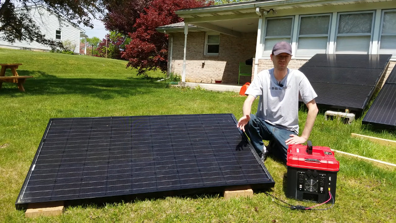
If you’re out in the wilderness, having plenty of electricity on hand is a blessing. Eschewing fossil fuels, [LithiumSolar] is, as their name suggests, a fan of other technologies – undertaking the construction of a 3.5kWh solar generator that’s rugged and ready for the outdoors.
The build starts with 18650 lithium-ion cells sourced from a recycler, packed inside obsolete modem battery packs. After harvesting 390 cells, the best 364 are chosen and assembled into plastic holders to create a 14S26P configuration. A spot welder is employed to weld the pack together, with XT60 connectors used as the main bus connectors, albeit in a very non-standard configuration. Balance leads are hooked up to a 14S battery management system, to keep things in check. The huge pack is then installed inside a stout Craftsman toolbox, along with a MPPT solar charger module, and a 1500W inverter for output.
The build video is a great resource for anyone interested in building custom 18650 packs or battery solar power systems. [LithiumSolar] does a great job of clearly explaining each step and the reasons for part selections along the way. Of course, in a neat dovetail to this project, we’ve even seen solar-powered spot welders before – which would be useful if you need to replicate this build out in the field somewhere. Video after the break.
[Thanks to Keith O for the tip!]


It’s a neat project, but I notices a few cringe-worthy items: the way the cells were being stored (haphazardly thrown in a box), the main power connectors depending on soldered connections instead of a physical connection, and that last bit where he had his clamp meter set to AC and was using it on a DC line. Other than that, it’s an awesome project. the case he’s using is part of a modular system that has a wheeled base or can be connected to a wheeled trolly (Versa-Stak or the Dewalt T-Stak system, which are interchangable.)
Will be much more than 3.5kWh when those 18650’s go off.
Have you really thought that statement through? 3.5 kWH is the total stored energy. Where is the extra going to come from?
There’s stored energy in all those hydrocarbons surrounding it, it’s just not so easy to release until you’ve got a lot of heat or some powerful oxidants.
I think we have different ideas of what constitutes “haphazard.”
The cells have shrink wrapping and an insulated positive end. It difficult and highly unlikely that there will be a short of a cell in a box like that. If there is a break in the shrink wrap and a cell makes contact with another cell then nothing happens because negative on negative does nothing.
That depends on how many other cells are in series before the negative terminal.
Oh no… another youtube video with no documents or anything to read, diagrams, nothing. Waste of electrons.
I spitball about 600W getting dissipated in there at max with only a crappy cheap looking fan, 20cfm??? Which since I see no obvious vents can only add it’s own 5 watts to the problem.
He has a push/pull fan system using 2 fans.
Output is to a 1500 W inverter. Does your spitball suggest an efficiency no better than 60%? In practice, it’s more like 90%, and power input 1700W, so maybe 170 W, at full load. The lack of vents is a bigger factor, but this will just limit the overall duty cycle. I don’t know what his typical use case will be, but in a solar-powered system, you typically can’t fully charge it more than once per day, and discharge it for the maybe 16 hours of non-charging time. This spreads 3500 W*hr / 16 hr = 220 W average, so the average power dissipation (i.e., heat-generating losses) over the discharge cyle would be no more than 25 W. Of course, it’s the length of those peak loads that produces the worst-case, but in most applications using 1500 W inverters, the full-load case would never be more than a few minutes at a time, such as operating power tools or microwave ovens.
Yeah, I would have put some cooling holes in both ends of the box, with flow-through ventilation.
18650’s are soooo ten years ago… There’s much better options for a project like this that wouldn’t require hundreds of cells to deal with… This has to be the most inefficient setup I’ve ever seen… What a cluster of chaos…
Any suggestions? Nearly every large-scale battery I take apart is 18650s.
EV batteries are excellent for DIY home energy storage.
And they often ontain 18650s
The Tesla does but many more use pouch or prismatic cells.
A good source is the Kia eNiro PHEV.
Hi Greg, I’m going to do a project like this soon and I’d love to hear your thoughts on these better options.
It would not have fit in that box, but I don’t see the box as all that much of an asset, but I would have opted to keep the cells in the containers they were in. It seems a lot of things were tossed out that you had to pay to replace.
The cells were in old modem packs in a 3s1p configuration, they are not individually balanced to similar voltage because the BMS in the pack sets a charging voltage that isn’t actually that close to total bare cell voltage. They are removed from modem packs because they have been sitting in storage not at storage voltage and some of them die because of that and the lack of good balancing in the modem packs. Assembling a new pack out of a bunch of old modem packs would be very bulky and troubleshoot heavy if you don’t process and test the cells individually and make a new module/ pack like the fell’a in the video did. What’s great about these packs is that because their original intended purpose didn’t need much or any cycling, the cells typically test as brand spanking new. Getting 2600mah cells showing 105-110% rated capacity with no self discharge and only costing 50-75¢ each, is why spending a little extra on salvaging the cells, testing, and assembling them into new packs with a dedicated BMS and box is worth it.
They test as brand new, but they’re not. When they’re years old, the electrodes are crusted over with a layer of lithium salts from the degrading electrolyte and they’re not many cycles away from dying.
Glad to hear of the issues, but like the project. Curious why even semi-pros put AC receptacles w Gnd, almost invariably, upside down. It’s like a varroa mite. It happened… and now it’s here to stay… Very odd.
On a three-prong grounded electrical outlet is the ground supposed to be down that’s what I thought and what is the reasoning for that
Recycled 18650’s
Cheap as chips.
That is the smart part.
beautiful stuff. But I don’t think it’s safe and thus can work :( .. unfortunately.
Living off grid and having played around with a number of “recycled” 18650’s I can strongly advice NOT!!! to use these and especially not if it’s over 100…
If they’re old and you don’t actually measure each individual cell one of those 360+ cells will drain and you get to experience stuff like current flowing reverse with all the interesting effects it would give.
Not sure how Tesla does it but I suppose the slightest off-voltages would disable cells or advice to have the cells balanced.
I can imagine with new 18650 batteries you are “safe” for a few years depending on the number of discharges, temperature etc.
Still you would have to measure the cells tediously every x months/weeks to be certain it’s a safe rig.
These are really my own unsubstantiated thoughts and chose to use 18650 maybe max 10 in a setup for mobile power.
Anyone agrees/disagrees? Would love to hear some input :)
I agree, using recycled elements will cause maintenance nightmares (or worse).
Any single element with a lower capacity will have a harder life than the other ones, and will soon degrade. Then, the other elements in parallel will have also a tougher life than the other ones, and will degrade sooner.
A smart BMS would allow to detect such a condition sooner, but anyway, identifying the culprit among 14 parallel elements will oblige to disassemble all the elements, and individually test each one.
Then another group of parallel elements will do the same….Good luck!
New identical cells, in smaller groups individually monitored would be a better option.
All the cells have been tested for capacity and matched with cells that are equal, most likely within 10mAh-100mAh range.
There is a huge market for second-life batteries and powerpacks like this.
If a cell within that parallel-stack is failing it will draw more power. the connection point from cell to cell can be designed in such a way that it will work as a fuse, thus automatically breaking the failing cell away from the rest of the pack. This break can then be detected by the BMS (if such thing is installed)
sad that there is no one like batteryhookup here in the UK :(
Lucky you.
+1
Do not know nothing of electric, s or electronic, s but it was the best film i have seen for years, well done mate i was enthralled from start to finish
no balancing? Can easily blow up
It has battery management with balancing described in the video.
I’m making something similar, but instead opted for: 2x deep cycle wheelchair batteries in series for 24v, a “Perfect Suitor” 30A MPPT instead of the shown MPT-7210A, and bought a bigger inverter (3000W Pure Sine inverter of the same manufacturer.) The cost was roughly the same, but I don’t have nearly as much energy density.
I think the bottleneck is always going to be the inverter though. High frequency inverters don’t seem to do so well with tools that require high current surge. The manufacturer of these inverters, WZRELB, even recommends that you select an inverter that is 2-3 times what you expect your surge to be, but I’ve found that even this isn’t always enough to run things like air compressors or an AC powered staple guns.
If you’re running purely resistive loads then this is great setup, but if you’re planning on running saws or air compressors you’ll probably want a much bigger, and probably low frequency inverter. I think at this point that’s where I’m going.
V/Hz ramp up does wonders for motor loads that are otherwise very hard to start.
Like a VFD? On my rig I plan on running a miter saw and and table saw as a portable thing in my barn. My solenoid hardware (AC staple gun and air compressor) I could potentially live without.
If you really want to run a machine shop skip the inverters all together – almost every tool is DC in function and the voltages are going to be in the same ballpark as most solar battery arrarys so you might not even NEED a buck/boost to run them.
I’d suggest getting tools designed for DC (battery operated for example) to save you much effort, but its not that hard to convert usually – just bypass the HV rectifier and go straight to the tools motor controller with the right voltage.
It will be way way more efficient as you are cutting out lots of conversion steps. And I always fancied making it so the tools ‘plug in’ with their standard battery location but to the huge power bank – meaning I can keep some charged standard battery and have a portable tool if I want to.