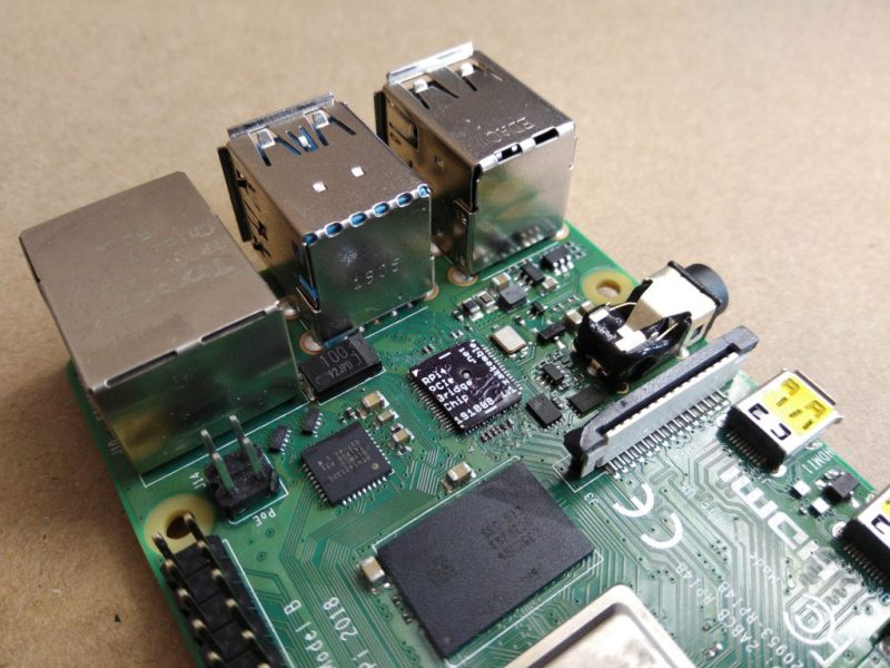
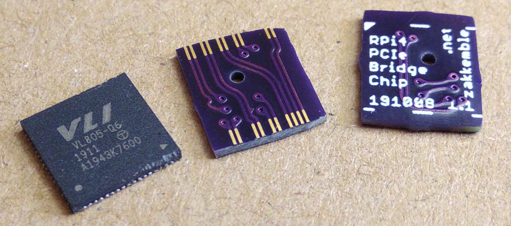
Ever since people figured out that the Raspberry Pi 4 has a PCIe bus, the race was on to be the first to connect a regular PCIe expansion card to a Raspberry Pi 4 SBC. Now [Zak Kemble] has created a new approach, using a bridge PCB that replaces the VL805 USB 3 controller IC. This was also how the original modification by [Tomasz Mloduchowski] worked, only now it comes in a handy (OSHPark) PCB format.
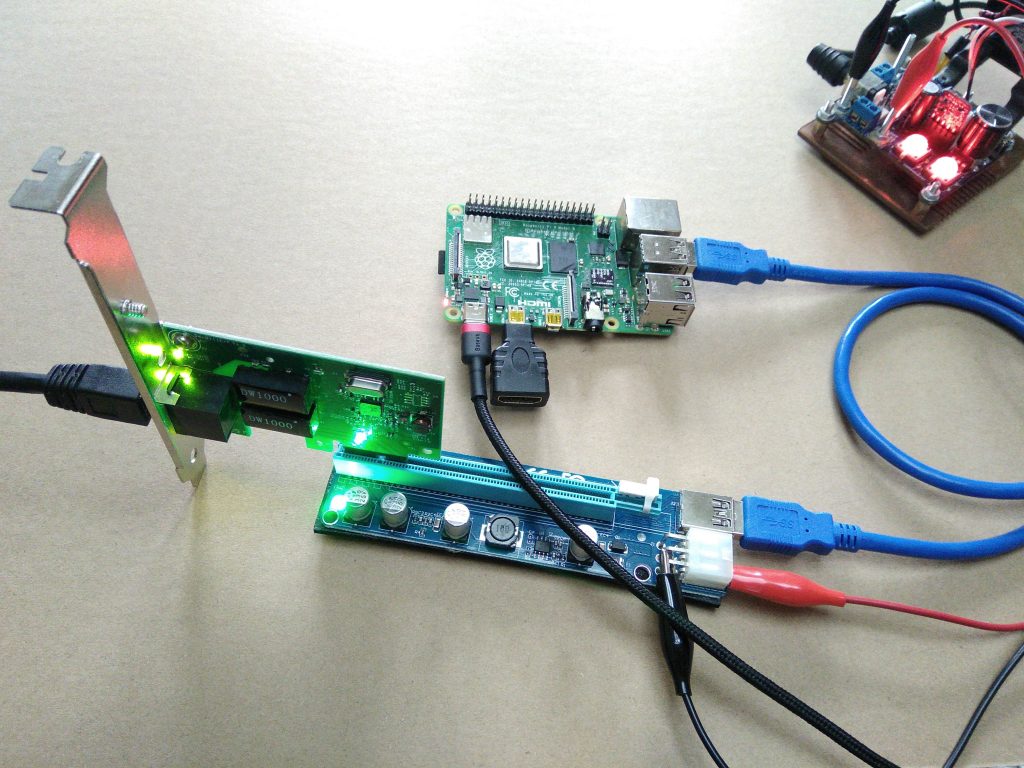
After removing the VL805 QFN package and soldering in the bridge PCB, [Zak] confirmed that everything was hooked up properly and attempted to use the Raspberry Pi 4 with a PCIe extender. This showed that the Raspberry Pi would happily talk with a VL805-based USB 3.0 PCIe expansion card, as well as a Realtek RTL8111-based Ethernet card, but not a number of other PCIe cards. Exactly why this is is still unclear at this point.
As a bonus, [Zak] also found that despite the removal of the VL805 IC from the Raspberry Pi rendering its USB 3 ports useless, one can still use the USB-C ‘power input’ on the SBC as a host controller. This way one can have both PCIe x1 and USB on a Raspberry Pi 4.
This is the third iteration we’ve seen for using PCIe with the Pi. If you’re building on the work of [Thomasz Mloduchowski], which inspired [Colin Riley] to add expanders, and now this excellent hack by [Zak], we want to hear about it!
(Thanks to Itay for the tip)


Molten plastic everywhere. Seems like that pi4 have seen some terrible things…
Should have used a few layers of kapton tapes as heat shield for those plastic parts. Also cover the tiny passives around the parts you are trying to remove as they might get displaced/blown off by the hot air tool by accident.
If you do not have kapton tape, two layers of Al foil also work quite good. Even when I had to solder on a speaker cone with a jet flame lighter (blue flame).
It seems backwards, but connectors and especially through-hole connectors are generally the most sensitive parts to heat. It’s really easy to end up melting them when trying to rework surface mount stuff with IR or hot air.
Very cool stuff. I hope you will figure out how to get it working with some gaming GPUs, that would be a gamechanger :-)
Also i wonder why the bridge board is not cut to some regular rectangular shape… Kinda bugs my OCD :-)
That will never ever happen, the cpu in the Pi4 doesn’t have enough BAR space. Maybe they’ll fix that with a refresh or the Pi5!
Not enough BAR space to do what exactly? Run games at 100 fps? 30 fps? It would be nice if that statement could be quantified.
BAR space is needed to initialize the card and talk to it. With insufficient space its a no go. That said older cards may work.
I was also under the impression you can define the BAR space in the software- ie its not baked into the chips. So it might be possible to make it work still.
Not an expert by any means so could be wrong. Even if it did work I don’t think even the impressive specs (for a SBC) of a Pi 4 could really drive a new GPU effectively – its going to be bottlenecked somewhere.
I see the PCI slot option being more likely useful for running multiple ethernet interfaces for example – so your next Pi cluster could actually use a Pi as its network switching, routing, dhcp server perhaps?
There are plenty of x86 mobos that don’t have a large bar. Think about it: modern gpus still generally support 32-bit OSs (even without PAE). Most of the time, the pcie config of gpus specifies 256MB, regardless of the size of the vram (this is specified in the vbios). For reference, the Pi4 has allocated 8GB of its physical memory map to PCIe.
There is a specification to move the BAR after boot (“relocatable bar”) but it is not universally supported, and configs larger than 256MB caused enough issues with some mobos to stay at the known good value. I am not certain how these map to arm/device-tree; it may or may not be supported. In any case most GPU drivers are written with the assumption that not all memory is accessible to the CPU at any given time.
If there are technical limitations stopping you from running a GPU on this hardware, this isn’t it. AMD’s ROCm site has some good info on this if you’re interested.
Imagine you want to scan a large poster (24″x36″) but only got a letter-sized feeder scanner 8.5″ wide (Pi4’s BAR space).
You just can’t fit that large required GPU address space into the tiny visible window the Pi4 has.
That would be why network cards & USB adapters work (needs tiny space for tiny packets) but not a GPU with 8GB+ of memory and commands aperture space.
Excellent, thank you.
About the non-rectangular shape:
“The fabricated PCB should be sanded down to the correct size, so that the cross-section of the copper pads can be seen at the edge of the PCB, just like on a QFN package.”
I realize this doesn’t quite answer your question; my guess would be that the sanding was done by holding the PCB between fingers, probably achieving partial fingerprint removal in the process.
I know it probably shouldn’t, but those rigid micro HDMI to HDMI converters make me uncomfortable
As for why some cards won’t talk while others will, I’m not sure. I dived in to PCIe after I inherited a PCIe FPGA board at work and concluded PCIe was evil, did not like me and i gave up
But Altera CvP is nifty
I’m sure it has nothing to do with running PCIe (version 2 I believe) over the bridge PCB, out through a USB port, over a (short) USB cable to the PCIe breakout board, which itself has its own slot – three pluggable interfaces. That’s surely going to degrade the signal somewhat, and maybe those devices need a better signal quality then the working ones? Maybe there’s a redriver on the PCIe breakout board.
I recently got hold of a PCIe switch and the two cards that didn’t work with the Pi also don’t with the switch, so I don’t think it’s a problem with the signals.
The Pi4 probably has too narrow of a link training window. In a PC implementation, the link training window is fairly long but in an embedded application like the Pi4, the link training window for the card are probably too narrow. I would say in order to solve this problem you would need access to change the Broadcom’s SoC link training register. Normally this is not published but if a talented hacker can reverse engineer a kernel mode Raspian patch to make it work. Others have mention signal degradation. That is certainly possible – you adjust emphasis on the line through the register but again, it is similar to my prior comments, you’ll need to hack the kernel.
I recently tried an AM1184e switch, but the two cards that don’t work with the Pi also don’t work with the switch, so bad signals probably aren’t the problem.
Agreed! Given the choice to buy one with a full size HDMI port, even if it means the board has to be slightly larger I would do so every time I intend to actually use the video output.
Then again, I would also love to be able to buy one with the connectors not already soldered on for slim builds.
And I’d like to be able to buy a cellphone with full-sized connectors too, even if it does mean it has to be more than twice the thickness.
But.. these things will never exist because nobody else wants them… or so the marketers would have us believe.
Well, they’re not available because “nobody wants them”. But you can never *show* interest in a product, because there isn’t one available to buy. Therefore nobody must want them because no one is buying them.
i cant stand micro versions of ports at all. they are always shearing off. curse you phone people!
It’s something I find irritating with tablets too. You’ve got a (relatively) large housing, so why can’t they put in a *full-sized” SD/MMC slot? It would make it easier to be able to swap in media sets, and not as easy to lose as the pinky-nail-sized microSD cards.
laptops*
The undetected cards could be solved by modifying the dtb:
http://labs.domipheus.com/blog/raspberry-pi-4-pci-express-it-actually-works-usb-sata-gpu/
I wonder if it’s possible to stick that ASM1184e PCIe switch (QFN64) into the RPi USB controller socket via an adapter PCB of some sort, and drive the four USB sockets on the Pi4 as the four PCIe I/Os directly.
You can buy a PCIe expander (with a switch) and use that as the card connected to RPi. From there, branch off additional PCIe risers. https://www.aliexpress.com/item/32860687153.html
Why not something more convenient?
https://fr.aliexpress.com/item/32827554033.html
It’s more tidy this way, no?
Not sure if that will solve the issue, but it certainly could (actually seems more likely than my initial reaction below)- Want to know more about what devices are and are not working (and how they are failing) to get a better idea of why.
I’d have expected the issue to be the less than ideal signal paths not being good enough myself (having used bad PCI extension cables before), though I’d have expected to still have the kernel show its existence in logs if not lspci – I don’t know if lspci would show a garbled device, but it should still have some evidence of something on the bus in the logs.
Really want to try this sort of thing, but I’m holding out for a hopeful release of the compute module based on a Pi 4..
I really want some of the extras only compute modules have for a project I have in mind. A project that would love a working PCIe expansion option too – though I’d need more than one PCIe slot I think, which will add an extra step or two.
This is crazy! I want to know a bit more about the PCIE socket board he has there. I’m amazed that such a thing exists with a USB input?!
USB3 connectors and cables are used to extend PCIe in hobby setups for some time. There are no actual USB3 signals runing over that. It is purely passive adapter, can be obtained online from usual suspects. This hack capitalizes on that, because rpi4 already has easy way to redirect PCIe wiring to onboard USB connector by simply bridging the USB controller chip.
It’s not USB input; it’s just an extension board that uses a USB3 cable as a convenient source of a few impedance-controlled differential pairs. There’s a corresponding board that’s supposed to go in the PCIe slot on a motherboard that’s being imitated by the bridge board and Pi’s USB socket.
Turns out the USB3 cable’s pretty much the first cheap cable that can be used this way, as it has *exactly* the right number of minimal connections: the super-speed RX/TX lines (also used for PCIe’s RX/TX), the original USB2.0 differential pair (used for the clock), and then 2 extra lines (vcc/gnd) used for PERST/WAKE, with the shield being used as the return.
It’s obviously crufty and there’s a bit of a hit due to USB’s different impedance standards, but PCIe’s got way more than enough margin to handle it.
before usb3 we would use sata.. :)
The USB controller has been replaced with a trace bridge, so the “USB cable” is just an extension cable for the PCIe traces.
The PCIe daughter board is from a PCIe extension set, which happens to use a USB 3.0 like cable with type A on both sides, probably to save on manufacturing costs.
It will not work with a real USB 3.0 port.
The only functional USB on the pi is the usb-c port.
They appeared around 2015 in response to demand from cryptocurrency GPU miners, who wanted to use all available PCIe interfaces on a motherboard, but couldn’t physically fit the large GPUs side by side as they would be 2 slots wide, and then really need more space for ventilation. Other extenders used ribbon cable and were shorter. The USB cable was just picked as a convenient high speed serial cable.
Thanks for all of your input(s)! I understood that it wasn’t an actual proper USB interface, but had no idea that the USB 3 connector was being used for other signals.
Nice hack. Maybe it could be even easier if he can drill plated vias at the border of the PCB, that will leave a vertical trace when the board is cut. But I do not know how well this technique will work for those thin traces (I have only used this technique with bigger drills).
“Castellated Holes” is the term you are looking for.
Vias are too big for that. Look at the picture
Not with the OSH Park design rules. I have done 1.27mm pitch and may be able to squeeze down to 1mm pitch. The via holes + annular ring for the via + copper to copper clearance will be too big to go to 0.5mm pitch that’s typical for QFN parts.
The vias helps, but aren’t really necessary.
Of course not with OSH park design rules but with laser drilled micro vias, similar is possible. But no castellated edges with 0,5 mm pitch.
I had to substitute something like 48 pin 0,5 mm pith quad flat pack with slightly smaller QFN (32 or 36 pin) + some 0402 components. So I designed a 10 mm * 10mm board that was populated with the components and soldered on the existing PCB like being a QFN itself.
It was a 1 cm² 6 layer board with microvias and blind vias and it was a nightmare for the PCB manufacturer (he had to do it 3 times) and it was a nightmare to solder on the main PCB in itself. But we managed to make a few prototypes, all that was necessary to decide if we want to change the main PCB for a new product.
There are edge plating/side plating
https://www.multi-circuit-boards.eu/en/pcb-design-aid/drills-throughplating/pcb-sideplating.html
The more specialized PCB fabs can do this as well as HDI (High Density Interconnect).
You can also try to make this on a flex PCB. Make the pads a bit longer and fold it 90 degrees to make the “plated edge” for easy soldering.
Has anyone checked to see if that USB3 chip implements ‘Alternate’ mode? Maybe you can simply ask it to pass the PCIE signals out onto the connector.
You can’t the BCM2711 only have 1 x PCIe 2.0 and the UCB-C is just USB 2.0.
https://heise.cloudimg.io/width/2000/q75.png-lossy-75.webp-lossy-75.foil1/_www-heise-de_/ct/imgs/04/2/7/4/3/7/8/1/RPi4-Block-e4359fdb4be588cf.png
That’s quitter talk, did you try iddqd or up up down down left right left right b a start ?
I think they mean can the VL805 be told in software to become a pass-thru
USB3 hasn’t Alt mode, the USB-C has it. But the RPI4 USB-C is just USB2 and power. The BCM2711 only has 1 x PCIe 2.0.
https://heise.cloudimg.io/width/2000/q75.png-lossy-75.webp-lossy-75.foil1/_www-heise-de_/ct/imgs/04/2/7/4/3/7/8/1/RPi4-Block-e4359fdb4be588cf.png
So maybe they can design a future model that replaces the USB3 connector stack with USB-C. Then adjust the wiring on one socket to support PCIE Alt-mode. Doing that would disable the rest of the USB ports.
“this way one can have both PCIe x1 and USB on a Raspberry Pi 4.”
So you can have your cake^H^H^H^H Pi and eat it too!
Ever since people figured out that the Raspberry Pi 4 has a PCIe bus, the race was on…
That’s where I stopped reading.
Probably some reverse engineering nonsence of the Broadcomm shit.
Instead of this, I’d much rather use some board where the chips have actual datasheets.
This raspi thing is getting far to much credit, considereing there are some 100+ similar boards around
Lots of boards around, and for pushing the weird edge cases like this many of them might be a better choice. Though as I like the Pi foundation’s ethos I’d support them with my money.
The Pi’s win by a stupidly large distance for quality, support and community which makes the Raspberry Pi and its Foundation deserve all the credit it gets. Its also very well documented – not 100% open but almost no if any SBC out there is – always that blob for this chip/feature in there somewhere.
Also open and functional are very different things – do you really want to spend days tinkering and compiling just to get to a boot screen or using the install image made that is hopelessly out of date on the alternatives? I’m sure some of them won’t be that bad to get going, but many of them are worse and I’d rather get something reliable to build from I know works than spend months trawling the web for info on the weird options out there.
You really want properly open go for the FPGA and Risk V cores and do all the work yourself (thus being sure everything is ‘documented and works’)- which does sound kind of like fun. But you want to just get on with a project throw a Pi in has become a default for a reason – they are damn good!
Those alligator clips are making me nervous.
Heh, I see what you mean. The black one really looks like it’s touching two of the pins on the connector.
Which IIRC is fine, the top row 3 pins is ground, the bottom row 3 is 12V.
What you don’t want is lever the black clip into the bottom row but that should just make a tiny spark and trip the bench PSU’s protection.
Tho if I was alligator-clipping this I’d have clipped ground to the metal bracket on the card where it wouldn’t short anything if accidentally yanked out.
Take a look at the PCIe tree configuration – I read on another hack that the Broadcom is set to expect one device with a specific Vendor ID. Allow the tree to have a depth of >4 and remove the Vendor ID(s) and you should be good to go.
Hmm, I wonder if that vendor makes a 1394 host IC.
This a nice work.
I have an old PC with a PCI card (Adaptec 2906) to connect a SCSI scanner (Agfa 1236s).
I’d like to know if there is any way to use on a Raspberry PI with this pci extender.
If this could be done, I would share my scanner on the local network, instead of looking for an expensive and unreliable usb to scsi adapter to connect to a modern pc.