Modern radio receivers have a distinct advantage over the common early designs which I covered in my previous article. Most of the receivers you will have worked with over the past couple decades are designs by Edwin Armstrong; regenerative, superregenerative, or most commonly superheterodyne. These are distinguished by a few fascinating key traits that bring both benefits and drawbacks.
Today let’s dive into Mr. Armstrong’s receivers. I’ll also talk about DC receivers which, despite the name, are not made to listen to batteries. These are receivers you are much more likely to encounter in modern equipment.
Regenerative and Superregenerative
The regenerative receiver is all about doing more with less. You still see some of these in simple applications like RF remote controls. The idea derives from how an oscillator works. In a simple way of thinking, an oscillator is an amplifier with enough positive feedback that any tiny signal at the right frequency will amplify and then, through feedback, continue to output over and over. If everything were perfect, then, an oscillator would have infinite gain at a given frequency.
Of course, things aren’t perfect, but they are close enough. You have to set the feedback network up just right to get the frequency you want. Also, things in nature tend to be linear, so it isn’t like the amplifier has no gain at the given frequency and then suddenly has infinite gain. The gain increases until it meets the Barkhausen criteria and achieves stable oscillation.
 In fact, sometimes we want to build an amplifier and find that it oscillates for some reason. Maybe that’s what made Edwin Armstrong think about the regenerative receiver. In it, an amplifier is pushed almost to the point of oscillation at the frequency of interest. This can result in a huge gain for a single tube or transistor. This was especially important when using low-quality active devices. For example, a tube capable of a gain of 10 without regeneration might amplify between 5,000 and 10,000 times when it was right on the edge of oscillation.
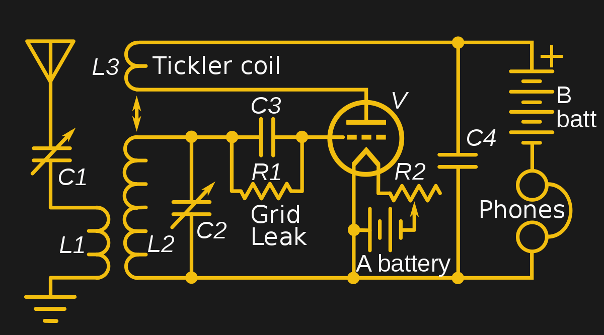
That’s a big improvement and meant that a very simple device could pick up very distant radio signals. There are many ways you could arrange positive feedback. However, the most common way (as in the accompanying schematic) was to have a pickup coil called a tickler around the primary tuned circuit coil. If that coil was out of phase, you’d get negative feedback, so common advice on this kind of radio was that if it didn’t work after you built it, try reversing the leads of the tickler.
The superregenerative was another design by Armstrong. It is essentially the same circuit, but after a certain frequency higher than the bandwidth of interest, the design stops the oscillation action allowing it to build again. Armstrong called this quenching. This could improve gains into the neighborhood of a million times. Armstrong’s original demonstration of the concept showed a three-tube receiver that was as sensitive as a nine-tube conventional design.
There are some downsides to both of these designs, though. You usually have to adjust the regeneration and the circuit can easily go into oscillation, producing a squeal. It also radiates signal back out the antenna, so it is a sort of transmitter. This is bad for interference or — for military applications — where you wish not to be found. If you want to build your own, we’ve had some advice for you in the past, including some on a breadboard. If you prefer, you can just simulate one that [Qrp Gaijin] demonstrates in the video below.
Superheterodyne
Armstrong was also behind the most successful architecture of all, the superheterodyne. If you have a non-software defined radio, it probably uses this technique. The idea is simple and has to do with selectivity. Consider the TRF radio. You can get better performance by putting more stages ahead of the detector. But each stage has to cover the entire range of the radio and requires tuning when you change frequency.
Armstrong’s idea was to limit that. You may or may not have one relatively broad filter in front of a mixer that adds (and subtracts) two RF signals. Then a local oscillator provides another signal to the mixer. Suppose you want to receive a signal at 1 MHz and you set the local oscillator to 9 MHz. You’ll get a signal at 10 MHz (and 8 MHz). You can now filter that 10 Mhz signal and amplify it using filters and amplifiers that you don’t have to tune (at least, not more than once). This makes their design simple and is also less hassle for the operator.
Now, if you want to receive a signal at 1.1 MHz, you change the local oscillator to 8.9 MHz. You still get a 10 MHz signal. If there is a station at 1.2 MHz, you’ll also get a signal at 10.1 MHz, but since you have the 10 MHz filters and amplifiers, you can get rid of that easily. That 10 MHz, in this example, is the IF or intermediate frequency.
This is a great way to build a radio. You can pile on gain and selectivity by adding more IF stages. The only real downside, as I mentioned in the last article is the possibility of images. Because the mixer both adds and subtracts, you can hear a station at the wrong frequency. Consider our 1 MHz signal with a local oscillator frequency of 9 MHz. A 19 MHz signal at the antenna will also show up at the 10 MHz output of the mixer since 19-9=10, just like 1+9=10.
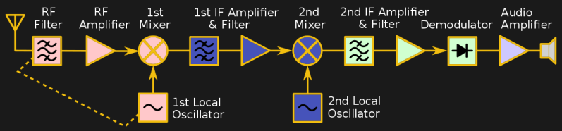
There are several ways to get over that. First, you can filter before the mixer. That’s why a lot of radios have a band switch — well, it is at least one of the reasons. You select a filter that roughly cuts out the interference from images. High-quality receivers will use dual conversion where one mixer produces one IF signal that is later mixed again to form a second one. Some will even use more conversions to optimize filtering.
There are several ways this can help. Image frequencies are always at twice the local oscillator frequency. Going back to the 1 MHz signal example, the image is at 2×9+1=19 MHz. So the higher the IF, the easier it is to filter off images. As a silly example consider if the 1 MHz receiver used an IF of 61 MHz. Now the local oscillator will run at 60 MHz and the image frequency will be at 121 MHz. It is trivial to filter 1 MHz from 121 MHz.
The problem is that using a higher IF makes it more difficult to reject stations adjacent in frequency. In our extreme example, filters to select between 61 MHz and 61.02 MHz are going to be more complex and costly than ones that select between 10 MHz and 10.02 MHz. Granted, there are surface acoustic wave filters and other devices that can do the job, but typically the best performance for a given cost is going to go to the lower frequency filters and amplifiers.
If you want a nice overview of the superheterodyne that isn’t too technical, check out the video below.
Direct Conversion
The direct conversion (DC) receiver has seen a resurgence in use since many software defined radios use this as a front end before digitizing the signal. You can think of a DC receiver as superheterodyne where the local oscillator doesn’t produce an IF, but instead is set to the frequency you want to receive. That means the output is the detected radio signal.
Using our 1 MHz example, to tune it in, you set the local oscillator to 1 MHz. The output is what you’d normally process with an audio amplifier (in the case of AM radio). The design has several practical problems. If the local oscillator isn’t locked to the transmitting station, the output will be incorrect. With SDR, that’s not a problem because the SDR software can track any shifts, but if you don’t have a computer handling things, it requires a lot of components to stay on frequency (essentially, a phase locked loop).
On the other hand, images are all at low frequencies and easily rejected. A lot of simple ham radio receivers use this technique because you don’t need a lot of frequency-specific amplifiers and filters that require tuning.
Getting Started Receiving
If you want to start designing receivers, the best bet is to build some and see how they work. It is hard to beat the simplicity and performance of a regenerative receiver. Sure, a crystal set is easier, but it won’t pick up like a regen. Using the NE602 or NE612 mixer is a handy way to make a direct conversion receiver with only a little more work. You can use that same mixer in a superhet design, but it is definitely more work.
Even if you are using SDR, you usually need some kind of front end. There are a few more exotic designs we didn’t talk about. If you want to read about Hartley, Barber Weaver, and other interesting topics, A Texas A&M presentation on the topic will fill you in.
Of course, the best way to learn is to go build something! There’s no shortage of design ideas for every kind of radio we’ve discussed. Once you start tweaking on real hardware, you’ll quickly find out what works and what doesn’t.
Acknowledgment: Most of the pretty pictures of block diagrams and schematics were adapted from public domain sources on Wikipedia, particularly from [Chetvorno]. What a great resource.


I thoroughly documented the design and construction, from scratch, of a Direct Conversion receiver that can be used on any HF band on my site: https://miscdotgeek.com/building-direct-conversion-receiver-part-1/
A Q multiplier was a common way to improve selectivity of a superhet through regeneration.
But didn’t Armstrong show how to make vacuum tube oscillators with his regen work?
I’m not sure, but that’s the way I read it years ago.
Direct conversion receivers are like the regen when it’s oscillating. Not the same topology, but results the same. When the name came along, it was about receiving CW and SSB, where you need the beat, and mistuning not really a problem.
Fifty years ago, Signetics introduced a line of analog PLL ICs, including the NE561, which had an extra balanced mixer for AM reception. Those were popular for simple AM broacast receiver projects.
Direct conversion does have a significant image issue, the image lands in the audio passband, exactly where the wanted signal is. The only way to filter out the image is to use a crystal filter on the signal frequency (which means the receiver is not tuneable), between the antenna and mixer. In the late sixties one ham did some work along these lines, actually direct conversion transceivers, but he was using them on nets, where you want everyone on a single frequency. Some simple receivers and transceivers projects for digiral work have used signal frequency crystal filters.
Audio images in direct conversion receivers is exactly the same thing as images in superhets. Get rid of the image with a good filter or use a phasing network.
I always admired the concept of the “reflex radio”.
A basic tuned circuit sends RF to a single transistor. At the output of the transistor is a high pass filter, and a low pass filter.
RF goes through the high pass filter, gets rectified by a detector diode, smoothed by a capacitor – then gets fed back into the single transistor, now as an audio frequency.
As audio, the signal goes through the low pass filter.
But that’s”s just a way of using parts, not a new reeiver design.