A few years ago, I needed a teeny, tiny potentiostat for my biosensor research. I found a ton of cool example projects on Hackaday and on HardwareX, but they didn’t quite fulfill exactly what I needed. As any of you would do in this type of situation, I decided to build my own device.
Now, we’ve talked about potentiostats before. These are the same devices used in commercial glucometers, so they are widely applicable to a number of biosensing applications. In my internet perusing, I stumbled upon a cool chip from Texas Instruments called the LMP91000 that initially appeared to do all the hard work for me. Unfortunately, there were a few features of the LMP91000 that were a bit limiting and didn’t quite give me the range of flexibility I required for my research. You see, electrochemistry works by biasing a set of electrodes at a given potential and subsequently driving a chemical reaction. The electron transfer is measured by the sensing electrode and converted to a voltage using a transimpedance amplifier (TIA). Commercial potentiostats can have voltage bias generators with microVolt resolution, but I only needed about ~1 mV or so. The problem was, the LMP91000 has a resolution of ~66 mV on a 3.3 V supply, mandating that I augment the LMP991000 with an external digital-to-analog converter (DAC) as others had done.
However, changing the internal reference of the LMP91000 with the DAC confounded the voltage measurements from the TIA, since the TIA is also referenced to the same internal zero as the voltage bias generator. This seemed like a problem other DIY solutions I came across should have mentioned, but I didn’t quite find any other papers describing this problem. After punching myself a little, I thought that maybe it was a bit more obvious to everyone else except me. It can be like that sometimes. Oh well, it was a somewhat easy fix that ended up making my little potentiostat even more capable than I had originally imagined.
I could have made a complete custom potentiostat circuit like a few other examples I stumbled upon, but the integrated aspect of the LMP91000 was a bit too much to pass up. My design needed to be as small as possible since I would eventually like to integrate the device into a wearable. I was using a SAMD21 microcontroller with a built-in DAC, therefore remedying the problem was a bit more convenient than I originally thought since I didn’t need an additional chip in my design.
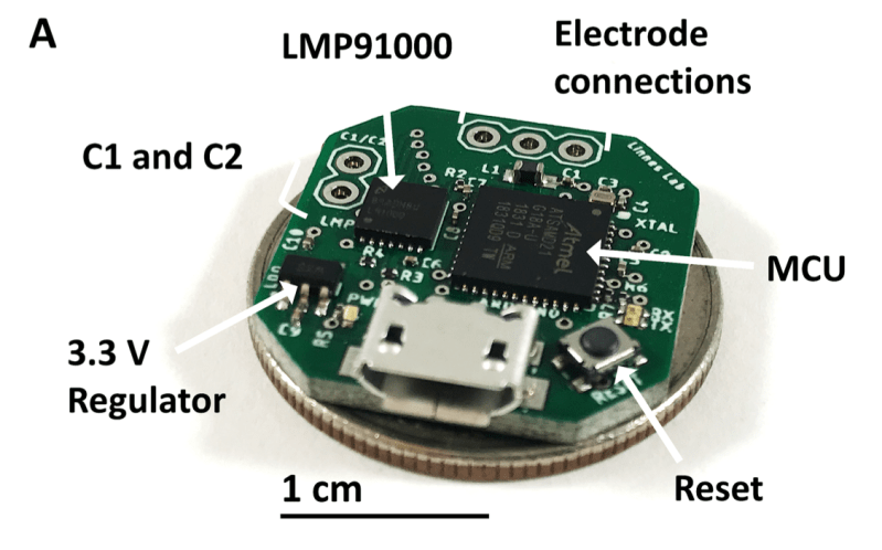
I am definitely pretty happy with the results. My potentiostat, called KickStat, is about the size of a US quarter dollar with a ton of empty space that could be easily trimmed on my next board revision. I imagine this could be used as a subsystem in any number of larger designs like a glucometer, cellphone, or maybe even a smartwatch.
Check out all the open-source files on my research lab’s GitHub page. I hope my experience will be of assistance to the hacker community. Definitely a fun build and I hope you all get as much kick out of it as I did.


Cool project. Wonder if you could use an MCU with a built-in TIA; maybe something like an MSP430FR2311? It has a dedicated TIA and a focus on low power consumption, along with GCC support and an Arduino fork called Energia.
Those chips are metal AF. Literally, they have ferrous non-volatile RAM.
“Ferroelectric” doesn’t mean ferrous; it’s just an analogy to the persistent polarization of ferromagnetism. It’s perhaps not the best choice of name ever. The ferroelectric material in FRAM is some sort of ceramic, I believe.
Two common substances are PZT (PbZrTiO3) and SBT (SrBi2Ta2O9)
And indeed, the hysteresis curve is analogous to the one for ferromagnetic materials, but aren’t ferrous.
That said, Lead is fairly metal:)
Do you need the xtal? They seem like an unnecessary BOM expense and assembly fiddle if you don’t have massively fast serial comms. Crystalless SAMD21 cores are perfectly usable for USB upload in my experience. I think mattair tech do one for the xeno you could check out.
Thanks for introducing me to the potentiostat, its applications and some core design considerations.
I’ve been wondering if I could remove the XTAL, but haven’t dug into it as yet. Great suggestion. Glad you enjoyed the article. Be sure to take a look at the original research article and I think you’ll find this article by the Wheeler Lab to be pretty interesting too
“DStat: A Versatile, Open-Source Potentiostat for Electroanalysis and Integration” doi: https://doi.org/10.1371/journal.pone.0140349
I just wanted to say thanks for the work. Hopefully this is another brick in trying to build open-source alternatives to expensive medical equipment.
A lot of people are locked out due to costs, or have to participate in special studies and ‘competitions’. In the end, it is all of us that pay for the markup, and our friends and families that miss up on a better life. GCM (for example) is a luxury that should not be a luxury.
This is really cool project, thanks for sharing. Could you guide on where the SWD header pins go? I couldn’t locate them on the pcb file. thank you
They’re on the back, under the microcontroller. The hardware files aren’t the easiest to find due to a project name clash that makes the repo look like it’s for a different device.
Hi, Mr. Hoilett. We are trying to operate a potentiostat of this using the LMP91000 with the Arduino and a DAC MCP4725. These are components that we have available here in Brazil. There are some doubts about this. 1) In the LMP91000 data sheet, is there a minimum limit for the Vref of 1.5V and, therefore, the resolution between 0 and 0.36V will only be that of the LMP? 2) I saw in your KickStat article that you solved the internal zero change by subtracting the internal zero value from the TIA measurement result and dividing this by the feedback impedance. What would this impedance be (sorry for my ignorance about it)?
I managed to make it work. It was a little bit of work, but it worked. The doubts are now different: 1) And the negative bias? In the getCurrent method you use Vref for the calculation. However, my Vrefs are positive and the LMP that makes them negative (through setNegBias ()). Do I have to put in the code that Vrefs are negative? 2) I noticed that the minimum external Vref supported by the LMP is 1.5V, which leads to an interval in the polarization sequence, jumping from -0.030V to 0.030V, in the case of my code. How to eliminate this?
If somebody built and use this potentiostat, please drop me a line. I have several questions. I am not expert “only” chemistry teacher. Istvan Vamos from Budapest (istvan.vamos@gmail.com)