These days, when doing any sort of optical tracking, our mind immediately leaps towards sophisticated solutions. Raspberry Pis, high end cameras, and machine learning toolchains all come to mind. Of course, if your goals are simpler, you needn’t complicate the issue. PHIL is a light tracking robot who is perfectly happy to do it the old-school way.
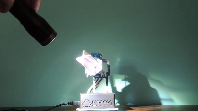
PHIL consists of an Arduino Uno running a twin-servo motion platform, providing the sensor head with pan and tilt functionality. The sensor head itself consists of a 3D-printed cruciform-section shroud that mounts four light-dependent resistors in individual sections. The shroud helps block light to the off-angle sensors, giving a stronger difference between those exposed to the light directly and those on the dark side. This makes for a stronger difference signal, so when the Arduino reads the sensors, it’s much clearer which way PHIL should point the sensor head to follow the light.
The builder, [Sean O’Donovan], notes that PHIL was built with no practical purpose in mind, and is simply a cool project. We certainly agree, and it’s important to note that skills picked up on a project like this will invariably come in handy down the track. Such techniques can be highly useful for tracking the sun, for example. Video after the break.


I have seen this done with solar panels with rotating axis. The longer the light deflectors before the detectors. The better the positioning becomes.
Also NO need for external power as the panels power directly the (dc) motors.
Just what I need, I had this idea too, was initially thinking of using the time of day, but this method might be less hassle. Of course I would do it with analogue components, it’s easier to make it work in all weathers. Accuracy doesn’t need to be spot on, as cos(20deg) is still 94%, so +/- 10 degrees is easily good enough.
I tried it, problem is when it’s not that sunny, very cloudy, the system has no idea where to go.
Best result I had was with time and encoders on axis (although if you have a rigid link, encoder on motor would be easier).
In my case I had a pulley and if it was to windy it would drift and don’t catch back.. (And I was afraid that a rigid link would put to much stress on the panel).
I also tried a magnetometer and accelerometer instead of encoders but all the metal around and power had a negative effect on the precision.
Really, you will have less hassle with an encoder (as5600 is 2$ on aliexpress, sadly only 1 i2c address is available, you can use a i2c multiplexer or just toggle the clock line)
Digital sun dial anyone? Depending on the position of the sun, light up the right digits on a seven segment display. You could probably get at least quarter hour accuracy. Maybe even better. Although seasons and position on the earth would need to be factored in, nearly negating the reliance on the sun for time. A GPS signal or other automatic solution like a RTC would be the easiest sources of that information, and they include the time already. Hmm.. another pointless project no doubt. Thoughts?
Would be cool, fun, and educational. You don’t need anything more as an input than your position on the earth, so that’s a one-time setup thing — no GPS really needed.
Or, you could invert the problem. Use an RTC, so you know the time, and then back out your location from following the sun.
Jaromir did this with just the sunrise/sunset times: https://hackaday.io/project/28550-light-level-geolocator (Still one of my favorite projects for its beautiful simplicity.) Mattias Koch riffed on this with one using different colored LEDs as the light sensors, letting him get some spectral data in the mix.
Here, you’ve got _much_ better information, and lots of it. Assuming you can level and orient the device, I bet you can figure out your location fairly accurately. That would totally be worth trying.
To be truly pointless it would have to display a QR code of the time.
I built one of these about seven years ago. They’re tremendously fun to play with and watch them track light sources, and mess with the ADC priority and see how that changes the tracking behavior. When 3d accelerometers got cheap I stuck one on the detector plane and had the arduino reading and recording that (which measurably slowed down its response speed.) They’re a critical part of an accurate heliostat.
Here’s mine wandering around: https://www.youtube.com/watch?v=NIYycBw7dfo
Now I’d do it all 3d printed, but at the time I was still fabricating everything out of aluminum.
We did that same thing some years ago.
I like your implementation :)
https://www.youtube.com/watch?v=egF929u2DCk
Can I know how did you do it how many motors did you use?
could you make a Sunflower Terminator sound any less cool?
Obligatory comment coming: could do it with a 555 :) Actually, it would be fun and educating :)
probably opamps in comparator mode. i figure it would take 4 of them (though you can get packages with multiple opamps). then you would have to go though the trouble of motion control through analog means. though you could just use an attiny85 (assuming you disable the reset pin) could receive all four analog channels and produce two servo pwm signals. i usually spring for the solution with the lower pin count.
Even simpler: One could modify each RC servo to replace the feedback potentiometer by the two opposite LDRs connected in series. The stable position would be the one where both LDRs receive the same illumination, and have the same resistance.
ive seen this method used to aim heliostats at the sun. get more out of your solar panels.
I used to work for a company that had a patent on this. It was developed into an airborne missle defense system.
I remember working this problem 30+ years ago in my control systems class. All op-amps and analog signals. Not even a 555 in sight :)
I cannot help but feel that “traditional geeking” is dying out. Something like this needs 3D printing and Arduino? I did this probably 20 years ago with LDRs and transistors (not even any ICs), purely discrete parts and analog. Where is knowledge like this going? Why does literally everything these days have to have an Arduino/RasPI/AVR/PIC/etc.? Do people not know how to solve even simple “maker” problems without such devices? Asking for a friend, of course.
in the next 20-30 years people wont even write codes, but ask an AI agent to “Make this follow a light”, and it will generate the circuit, send to PCB manufacturer with all parts sourced and assembled of course, write the code, and you just get the thing in your mail – by a drone.
And by them we gonna say “back in my day, I had to add an IC, program it, upload the sketch, wire up all by myself in a breadboard (anyone?) and run 5 to 10 interactions until get it right. PID and Inverse kinematics?… uff, it was crazy when come to tune that, but THAT was REAL geeking!!! not this AI stuff”
In 40-50 years we have time machines, and I can tell you remarks like that are written by bots reminiscing about the old days when someone used to ask them to design a PCB….
Anka, You have just won the internet for today 😂
I know, and I get it, but it just seems that with everything done by computer these days, the fun is somehow gone. Can’t tell how many times I thought, hey, this or that would be a great project, only to find that everything was implemented by code. It lacks a certain “je ne sais quoi”. it just seems like all this is too easy, and while the goal was achieved, there was no challenge to it. Oh well, oh fa*t talking here, I guess it’s time to move aside with my outdated “knowledge” and “experience”…
20 years ago, a friend built one to control his solar panels, but since it was before CBC hot glue guns he put the LDR’s in short pieces of PVC pipe.
At first he just controlled one axis, but later added tilt (not much to gain there if you manually adjust tilt for season)
Nearly identical to a college project I did in 1972 although mine was old-school and analog: LDRs>opamp>bipolar transistors>DC hobby motors with a fully gimballed x/y mount.
Interesting point is that LDRs have a very large range of light sensitivity and resistance. Some of these have minimum resistance of a few hundred ohms fully illuminated and 10 M ohm when dark.
Rather than making a voltage divider of the LDR with a 10K ohm resistor, if you make voltage dividers with 2 LDRs (1 divider for the 2 X axis LDRs and 1 for the 2 Y axis LDRs) you can actually use the huge dynamic range of these devices as the voltage readings are the result the differential illumination of the LDRs. (not the result of an LDR and a fixed resistor)
The one I built had phenomenal sensitivity. At high brightness it worked as expected but at low brightness source in a darkened room it could track:
The reflection of a penlight approximately 5 feet from a green chalk board (remember those?). The illuminated dot on the chalk board was about 4 inches in diameter and the tracker would track motion of the green dot from 20 feet away .
Track a lit candle from 30 feet away.
If you wrap a light shield around the base of the cruciform light shield it will create a “capture effect” and track a light in the presence of a surprising amount of ambient room light.
Nice article.
The bit I liked most about the design, is probably what no one else is looking at. It was the addition of capacitors to the servos to stop their power draw when incremented from either causing a brownout and possibly reseating the Arduino, or just not enough power being available when required and failing to increment the servos.
Could this be adapted to pinpoint an audio source?
I like watching the birds sing in the trees around my house, but it’s often very hard to find exactly where the bird is before it flies away. If it could pinpoint an audio source, attaching a low power laser pointer could show where the bird is located.