One of the biggest challenges for wireless sensor networks is that of power. Solar panels usually produce less power than you hoped, especially small ones, and designing super low power circuits is tricky. [Strange.rand] has dropped into the low-power rabbit hole, and is designing a low-cost wireless sensor node that runs on solar power and a supercapacitor.
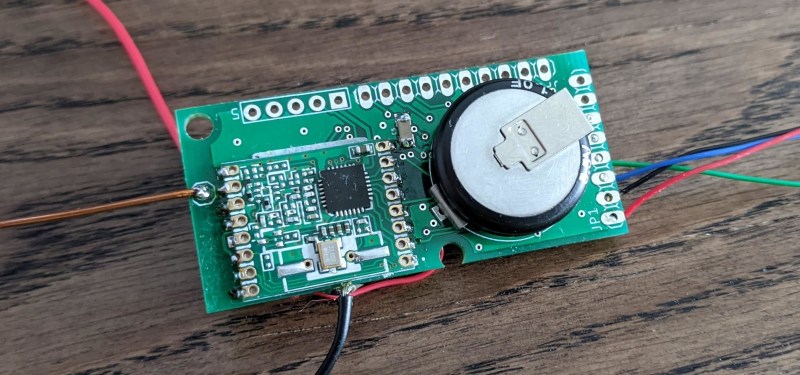
The main components of the sensor node is an ATMega 328P microcontroller running at 4Mhz, RFM69 radio transceiver, I2C temperature/humidity sensor, 1F supercapacitor, and a small solar panel. The radio, MCU, and sensor all run on 1.5-3.6V, but the supercap and solar panel combination can go up to 5.5V. To regulate the power to lower voltage components a low-drop voltage regulator might seem like the simplest solution, but [strange.rand] found that the 3.3V regulator was consuming an additional 20uA or more when the voltage dropped below 3.3V. Instead, he opted to eliminate the LDO, and limit the charging voltage of the capacitor to 3.6V with a comparator-based overvoltage protection circuit. Using this configuration, the circuit was able to run for 42 hours on a single charge, transmitting data once per minute while above 2.7V, and once every three minutes below that.
Another challenge was undervoltage protection. [strange.rand] discovered that the ATmega consumes an undocumented 3-5 mA when it goes into brown-out below 1.8V. The small solar panel only produces 1 mA, so the MCU would prevent the supercapacitor from charging again. He solved this with another comparator circuit to cut power to the other components.
We see challenges like these a lot with environmental sensors and weather stations with smaller solar panels. For communication, low power consumption of a sub-Ghz radio is probably your best bet, but if you want to use WiFi, you can get the power usage down with a few tricks.


This is awesome! I wish these were a finished product you could buy!
The RFM69 has a lot of potential that isn’t used. Everyone talks about LoRa and Bluetooth, but plain FSK is a lot faster than LoRa, and you can do your own error-correcting codes for a bit more range.
Bluetooth has a great low power mode that still allows receiving commands, but that can be done in software. Pretty much all the cool modern protocol features(OTA pairing, encryption, etc) fit just fine on an AVR in software.
For now, the 915MHz band doesn’t seem to have gotten trashed by overcrowding, and with dynamic transmit power control, I think there’s enough bandwidth for everyone even if it makes it to consumer IoT.
Agreed! Using the RFM69 means a nose can boot/wake up from sleep, read a sensor, transmit, and go back to sleep in a millisecond or two! No WiFi negotiation means low and predictable latency. Plus the radio uses an order of magnitude less power than WiFi, much more friendly for battery-powered devices.
I’m working on a low-cost RFM69-based battery-powered light dimmer switch right now, and if everything goes according to plan (hah), I should get a couple years of use out of a single CR2450 cell. Range wise it works everywhere in my small 3-story split level.
The 433/868 bands are ideal for such sensors. I am using RFM69 at 868 MHz and they work much better than the 2.5GHz ones. Lora is overkill for home, but would work just as well.
I would say 20-50 ms is more feasible for a transmission that has reasonably low bw (high range) and waits for an ACK. If you drop the ACK and really send minimal information, then indeed you can be looking at a few ms of active time.
There are a few selling RFM69 sensor nodes. Not with supercaps, but battery though.
There are some from lowpowerlab, adafruit, quite a bunch on tindie and plenty of open source deigns on openhardware.io
Sadly they’re mostly lithium-ion, with it’s calendar life issues. I’m got my boards back from the fab for an LTO version that should last 30 years on solar, but…. I wrote the protocol and designed the board during quarantine, and then ran out of time and started working again.
Woa. How come you need the things to last so long?
My problem with RFM69, nRF24 and similar boards is the custom nature of it. It’s fine if you build at least 2-3 gadgets and one gateway, but it’s annoying to just have one pair do one thing only. And it also means you cannot just buy a generic gateway for rPi for example, or a make a simple bridge to WiFi.
Right now my house automation is going into integration hell with various RF433 protocols, IR, WiFi, BT, nRF24 and another chip also working on 2.4 (similar to milight). I’m actively avoiding any new transceivers such as ZigBee, LoRa and RFM69, until the “market” stabilizes a bit.
https://hackaday.com/2020/09/15/deep-sleep-problems-lead-to-forensic-investigation-of-troublesome-chip/
Very cool – supercapacitors are promising but the linear voltage curve is annoying. Could you feed a 3.6V buck/boost converter into a 3.3V LDO to get a stable DC source for radio stuff? Or does the RFM module have its own LDO that could accept an SMPS?
I was thinking the same thing: this seems like a good place for a switcher. (Although switchers have terrible efficiency at less than 30% of their rated load, but really great at 50%-80%.)
I tried that, but here’s the deal: at the low currents consumed most of the time by the module (µA) the switcher is so inefficient that you are still better off with a low IQ LDO. For example a MCP1700 is rather cheap and common and only consumes 1.6uA. What can flip the balance in favor of a switching regulator is if you have a higher input voltage (>>3V) or the module spends more time in active (mA current).
Yeah, I was thinking about that later, and thinking about increasingly unlikely ways of enabling/disabling the switcher as it cycled between power states.
There’s still a place for LDO’s. I work in switcher design, and my company still makes a huge number of linear regulators.
There’s SMPS optimized for devices that have bursts of high current during transmission events and then minimal current in between such as the LT8636.
There may be, but that LTC in particular surely is not it. Do you have another part in mind maybe?
This is a great project. Is it going to be commercially available ? I have a Davis Vantage Pro 2 weather station. The station uses a solar panel to charge a super capacitor which provides power at night or on cloudy days. There is a lithium battery for extended low sun days. The station transmits data every 2.5 seconds. There is a place for a second supercap which I heard can run the station without the lithium battery backup.
Just as a reference, given that the Q=V*C, if you draw the supercap down with a constant current-drawing buck power supply, that would of course see linearly dropping off supply voltage, the equivalent capacity for a 5V, 1F circuit is 1.4 mA hr.. Such hypothetical constant current supply wouldn’t of course work all the way to zero voltage, so the actual usable capacity is probably around 1 mAhr. Not much….
The good news is that the supercaps are getting larger—$14 can get you 4.2V 90F ( MAL219690101E3 ), providing around 75 mAhr