The Raspberry Pi Compute Module 4 has got many excited, with a raft of new features bringing exciting possibilities. However, for those used to the standard Raspberry Pi line, switching over to the Compute Module form factor can be daunting. To show just how easy it is to get started, [timonsku] set about producing a quick and dirty carrier board for the module at home.
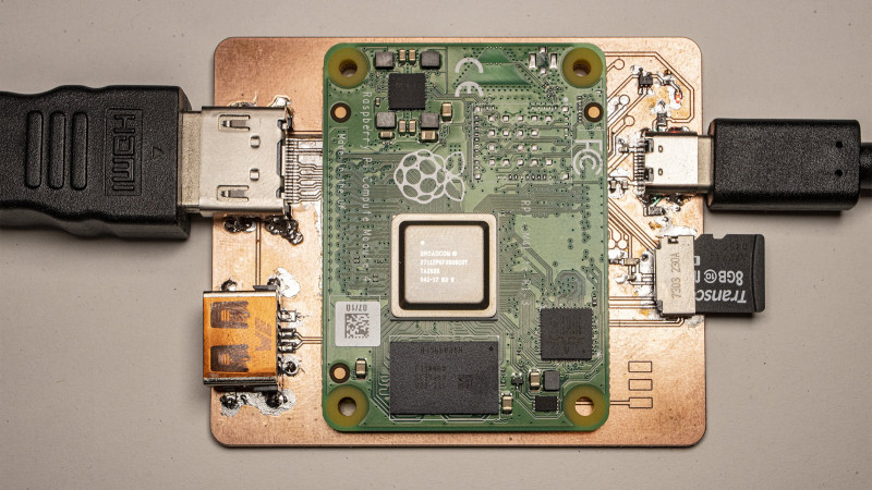
The Twitter thread goes into further detail on the design of the board. The carrier features HDMI, USB-A and USB-C ports, as well as a microSD slot. It’s all put together on a single-sided copper PCB that [timonsku] routed at home. The board was built as an exercise to show that high-speed signals and many-pin connectors can be dealt with by the home gamer, with [timonsku] sharing tips on how to get the job done with cheap, accessible tools.
The board may look rough around the edges, but that’s the point. [timonsku] doesn’t recommend producing PCBs at home when multi-layer designs can be had cheaply from overseas. Instead, it serves to show how little is really required to design a carrier board that works. Even four-layer boards can be had for under $10 apiece now, so there’s never been a better time to up your game and get designing.
For those eager to learn more about the CM4, we’ve got a full breakdown to get you up to speed!


That’s some excellent homebrewing.
Yeah, just two decades ago this would have been a very neat PCB for hobby project. Nowadays it is “quick and dirty” :)
I would try to devise some way to affix a heatsink in it, with the same screws serving to fix the CM4 to the mainboard.
Other than that, not so rough as he says. The trace length for the HDMI connections could be calculated, if his pcb software doesn´t already offers that option.
A possible problem would be routing some things, when the pinouts would interfere with each other, but for many use cases one can judiciously choose which interfaces to implement, so that that could be solved. Also, two layer boards are not that hard to do at home, and there are many places to get boards made in the country, for those that do not want to do the work themselves.
You could make that board a little bigger and run a heat pipe from the CPU top to the copper. That would spread the heat around quite well I would think. Make it double-side too and stitch the layers together for extra heatsinking.
The point wasn’t really about what you can do with a homebrew PCB but that impedance matching is not as complicated and doesn’t require very expensive board to do so :)
There is not even a reference plain under those HDMI signals, which by common rules should be horrible in terms of impedance matching, there is nothing worse for high-speed signals than a true single layer PCB.
The idea is that people feel comfortable to just try it with standard multi layer PCB and with simple tools like an impedance calculator and don’t stop because the topic sounds very intimidating when you start reading about it as a beginner. If you didn’t knew better you can quickly get the impression that this is impossible or very flaky on a normal 4 layer board which is not actually the case if some basics are adhered to that most EDA tools offer like length matching and pair routing.
Agreed 100%
“There is not even a reference plain under those HDMI signals, which by common rules should be horrible in terms of impedance matching,” Not the least bit true. The impedance is DIFFERENT if there’s a ground plane under it, but it can still be calculated, either way. Two parallel wires separated by an insulator and no ground is how we all used to hook up our TVs to their antennas, and that ran at much higher frequencies than HDMI signals do. But let’s be clear about this: the impedance is important. Because the CM has those wires at a certain impedance, and so does whatever HDMI cable you plug into this, if the impedance on this board isn’t anywhere near the same as the other two, you get reflections at BOTH transitions, which can make the interface unreliable, or not work at all. But I get it – this project shows that it’s really not super critical.
That is true of course but without a reference plane for impedance matching the required trace width would be larger than any of the two connectors at play here could support. The only reason this works out ok is because the traces are so short.
What I want to know is where in the world can you get a compute module 4? Nowhere seems to have any stock.
They are starting to ship. The best place currently is farnell but by end of november most shops should have stock.
More interested in the PCB mill machine and software used.
A Bantam PCB Mill with their default control software which does PCB cam.
Nice work, however no one can do this unless they have an early supply of CM4s mine is out to Nov 19… How did you get yours?
Those $10 PCBs may exist for some people, but over here in Canada the PCBs are $4 even with lead free finish. The killer is the shipping, $16. And then the shipping will probably take 3 weeks.
It would actually be cheaper and easier for me to make my own boards, but my mom doesn’t want me working with dangerous chemicals.
So don’t – milling and scribeing PCB’s are perfectly chemical free viable options.. I don’t know that anybody has managed to scribe for as fine a detail as you can etch at home – but scribing has been shown to do rather fine pitch quite well still. Of course both require some form of CNC to actually practically create boards. But small desktop PCB mill are pretty cheap.
Does meet the fussy mother criteria – no chemicals. Bit of practice and work with reference jigs and double sided looks very approachable too. (I’ve only ever etched so far myself – though all the neat milling and scribing setups seen here make me tempted to switch)
This would only work until the mother heard about the fiber glass dust.
SHHH!!!!!! Mothers always find something to complain about, no need to make it easy for them. The scribe based systems don’t really make any fibreglass dust it looks to me, seems they do just scratch the copper surface down too the substrate, (Also not much of a problem on most of these smaller machines – they all seem to either be enclosed so the dust will be easy to vacuum up after it has settled or have active suction systems which look reasonably effective)
I’m confused by this. Isn’t the purpose of the compute module to not have those connectors? Wouldn’t you just use the regular version if you wanted all the connectors?
The purpose of the CM4 is that you can pick and choose which connectors you do/don’t want, and bake them into a format which suits you. The CM4 can actually have a few more connectors than the standard B model (the 4B uses PCIe for the USB3 hub, but you could use it for something else; the CM4 has 2 DSI/CSI screen and camera connectors and there’s at least one instance of a compute module board using this for stereo video).
For physical integration it’s easier to click the CM4 onto your custom PCB and the route the desired connectors to wherever you want them than to try and buid your design around where the ports are on the 4B.
Exactly as Shoe says. Though that layout is one heck of alot smaller than a normal Pi4 with connectors only on two sides which many people would like (assuming I recall the modules footprint correctly I’d guess the longest edge is around the same as a normal Pi’s width, but i’m still waiting on mine to arrive).
I’m also looking forward to a cable or vera simple carrier board, with only USB C that also emulates ethernet (as raspi 4 does). So I can connect to my ipad and power it un via usb c. Something similar with this: https://www.raspberrypi.org/blog/connec … -ipad-pro/
Powerfull os and devine in small factor, to “complete” my ipad functionalities :)
Yeah right – $3,600 and a 20 week lead time. Bantam shmantam.
Another in-thread reply comment that gets dropped to the bottom of ALL comments. When are you gonna dump this horrible comment system Hack a Day?
This is great! The CM4 gives you a very low-profile computer, and lets you choose what connectors you want to add and where to add them. And switching to low-profile Hirose connectors I think was a good idea. With this see-how-simple-it-can-be project, that should remove much of the anxiety that has kept many hobbyists away from the compute modules.
I would like to buy this pcb…