UAV Flight Controller Saves Weight

When building autonomous airborne vehicles like drones or UAVs, saving a little bit of weight goes a long way, literally. Every gram saved means less energy needed to keep the aircraft aloft and ultimately more time in the air, but unmanned vehicles often need to compromise some on weight in order to carry increased computing abilities. Thankfully this one carries a dizzying quantity of computer power for an absolute minimum of weight, and has some clever design considerations to improve its performance as well.

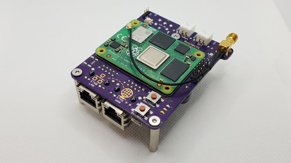
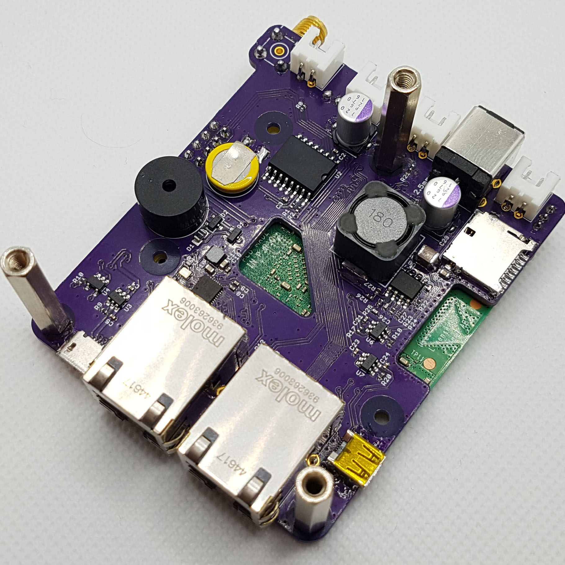
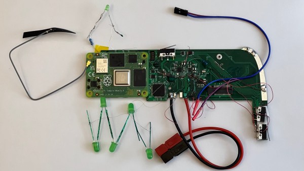
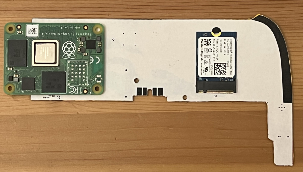
The advantage of this board compared to other similar offerings is that it is built to host a Raspberry Pi Compute Module 4, while the rest of the flight controllers are separated out onto a single circuit board. This means that the Pi is completely sandboxed from the flight control code, freeing up computing power on the Pi and allowing it to run a UAV-specific OS like OpenHD or RubyFPV. These have a number of valuable tools available for unmanned flight, such as setting up a long range telemetry and camera links. The system itself supports dual HD camera input as well as additional support for other USB devices, and also includes an electronic speed controller mezzanine which has support for quadcopters and fixed wing crafts.

Separating non-critical tasks like cameras and telemetry from the more important flight controls has a number of benefits as well, including improved reliability and simpler software and program design. And with a weight of only 30 grams, it won’t take too much cargo space on most UAVs. While the flight computer is fairly capable of controlling various autonomous aircraft, whether it’s a multi-rotor like a quadcopter or a fixed wing device, you might need a little more computing power if you want to build something more complicated.

Future Brings CPU Modules, And The Future Is Now

Modularity is a fun topic for us. There’s something satisfying about seeing a complex system split into parts and these parts made replaceable. We often want some parts of our devices swapped, after all – for repair or upgrade purposes, and often, it’s just fun to scour eBay for laptop parts, equipping your Thinkpad with the combination of parts that fits you best. Having always been fascinated by modularity, I believe that hackers deserve to know what’s been happening on the CPU module front over the past decade.

A Youtube thumbnail showing a Thinpad in the background with "Not Garbage" written over its keyboard, and one more keyboard overlaid onto the picture with "garbage" written on that one.
This “swap your Thinkpad keyboard” video thumbnail captures a modularity-enabled sentiment many can relate to.

We’ve gotten used to swapping components in desktop PCs, given their unparalleled modularity, and it’s big news when someone tries to split a yet-monolithic concept like a phone or a laptop into modules. Sometimes, the CPU itself is put into a module. From the grandiose idea of Project Ara, to Intel’s Compute Card, to Framework laptop’s standardized motherboards, companies have been trying to capitalize on what CPU module standardization can bring them.

There’s some hobbyist-driven and hobbyist-friendly modular standards, too – the kind you can already use to wrangle a powerful layout-demanding CPU and RAM combo and place it on your simple self-designed board. I’d like to tell you about a few notable modular CPU concepts – their ideas, complexities, constraints and stories. As you work on that one ambitious project of yours – you know, the one, – it’s likely you will benefit a lot from such a standard. Or, perhaps, you’ll find it necessary to design the next standard for others to use – after all, we all know there’s never too few standards! Continue reading “Future Brings CPU Modules, And The Future Is Now”

Motherboard on the desk, with a CM4 plugged into it, and all kinds of wires connected to it for purposes of debugging

Hackaday Prize 2022: A CM4 Upgrade For Your Old IPad

There’s no shortage of nicely built tablets out there, but unfortunately many of them are powered by what are by now severely outdated motherboards. Since manufacturers releasing replacement motherboards for their old hardware doesn’t look like its likely to be common practice anytime soon, the community will have to take things into their own hands. This is where [Evan]’s project comes in — designing a Raspberry Pi CM4-powered motherboard for the original iPad. It aims to have support for everything you’d expect: display, touchscreen, audio, WiFi, Bluetooth, and even the dock port. Plus it gives you way more computing power to make use of it all.

Testing part fitment with some cardboard CAD.

The original iPad got a lot of things right, a factor definitely contributing to its success back when it was released. [Evan]’s high-effort retrofit works with the iPad’s plentiful good parts, like its solid shell, tailored lithium-ion battery, eye-friendly LCD, and reliable capacitive touchscreen. You’d have to fit the new motherboard inside the space available after these parts all come together, and [Evan] has shaped his PCBs to do exactly that – with room for CM4, and the numerous ICs he’s added so as to leave no function un-implemented.

This project has been underway for over a year, and currently, there’s fourteen information-dense worklogs telling this retrofit’s story. Reverse-engineering the capacitive touchscreen and the LCD, making breakouts for all the custom connectors, integrating a custom audio codec, debugging device tree problems, unconventional ways to access QFN pins left unconnected on accident, and the extensive power management design journey. [Evan] has a lot to teach for anyone looking to bring their old tablet up to date!

The hardware files are open-source, paving the way for others to reuse parts for their own retrofits, and we absolutely would like to see more rebuilds like this one. This project is part of the Hack it Back round of the 2022 Hackaday Prize, and looks like a perfect fit to us. If you were looking for an excuse to start a similar project, now is the time.

Sketch of the two proprietary carriers showing their differences - one of them has a cutout under the antenna, while the other one does not.

Design Your CM4 Carrier With WiFi Performance In Mind

The Raspberry Pi Compute Module 4 has a built-in WiFi antenna, but that doesn’t mean it will work well for you – the physical properties of the carrier board impact your signal quality, too. [Avian] decided to do a straightforward test – measuring WiFi RSSI changes and throughput with a few different carrier boards. It appears that the carriers he used were proprietary, but [Avian] provides sketches of how the CM4 is positioned on these.

There’s two recommendations for making WiFi work well on the CM4 – placing the module’s WiFi antenna at your carrier PCB’s edge, and adding a ground cutout of a specified size under the antenna. [Avian] made tests with three configurations in total – the CMIO4 official carrier board which adheres to both of these rules, carrier board A which adheres to neither, and carrier board B which seems to be a copy of board A with a ground cutout added.

Graph plotting WiFi RSSI for each of the three carriers in each of the six locations. CMIO4 consistently outperforms both, while carrier B outperforms the carrier A, but by a more narrow margin.
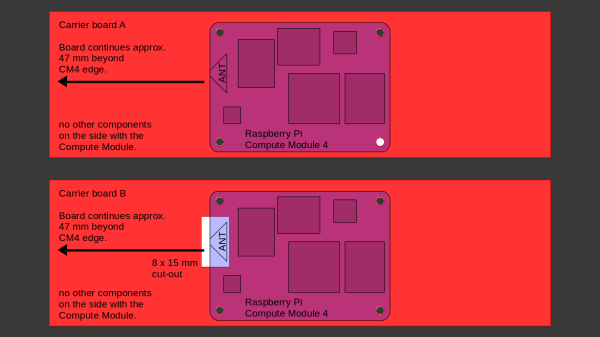
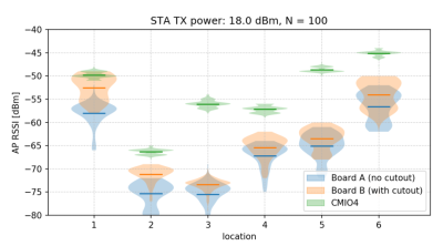
After setting up some test locations and writing a few scripts for ease of testing, [Avian] recorded the experiment data. Having that data plotted, it would seem that, while presence of an under-antenna cutout helps, it doesn’t affect RSSI as much as the module placement does. Of course, there’s way more variables that could affect RSSI results for your own designs – thankfully, the scripts used for logging are available, so you can test your own setups if need be.

If you’re lucky to be able to design with a CM4 in mind and an external antenna isn’t an option for you, this might help in squeezing out a bit more out of your WiFi antenna. [Avian]’s been testing things like these every now and then – a month ago, his ESP8266 GPIO 5V compatibility research led to us having a heated discussion on the topic yet again. It makes sense to stick to the design guidelines if WiFi’s critical for you – after all, even the HDMI interface on Raspberry Pi can make its own WiFi radio malfunction.

Meet The RouterPi, A Compute Module 4 Based GbE Router

[Zak Kemble] likes to build things, and for several years has been pining over various Raspberry Pi products with an eye on putting them into service as a router. Sadly, none of them so far provided what he was looking for with regard to the raw throughput of the Gigabit Ethernet ports. His hopes were renewed when the Compute Module 4 came on scene, and [Zak] set out to turn the CM4 module into a full Gigabit Ethernet router. The project is documented on his excellent website, and sources are provided via a link to GitHub.

A view underneath shows off the RTC, power supply, and more.

Of course the Compute Module 4 is just a module- it’s designed to be built into another product, and this is one of the many things differentiating it from a traditional Raspberry Pi. [Zak] designed a simple two layer PCB that breaks out the CM4’s main features. But a router with just one Ethernet port, even if it’s GbE, isn’t really a router. [Zak] added a Realtek RTL8111HS GbE controller to the PCIe bus, ensuring that he’d be able to get the full bandwidth of the device.

The list of fancy addons is fairly long, but it includes such neat hacks as the ability to power other network devices by passing through the 12 V power supply, having a poweroff button and a hard reset button, and even including an environmental sensor (although he doesn’t go into why… but why not, right?).

Testing the RouterPi uncovered some performance bottlenecks that were solved with some clever tweaks to the software that assigned different ports an tasks to different CPU cores. Overall, it’s a great looking device and has been successfully server [Zak] as a router, a DNS resolver, and more- what more can you ask for from an experimental project?

This CM4 based project is a wonderful contrast to Cisco’s first network product, which in itself was innovative at the the time, but definitely didn’t have Gigabit Ethernet. Thanks to [Adrian] for the tip!

A pinout diagram of the new Pi 4, showing all the alternate interfaces available.

Did You Know That The Raspberry Pi 4 Has More SPI, I2C, UART Ports?

We’ve gotten used to the GPIO-available functions of Raspberry Pi computers remaining largely the same over the years, which is why it might have flown a little bit under the radar: the Raspberry Pi 4 has six SPI controllers, six I2C controllers, and six UARTs – all on its 40-pin header. You can’t make use of all of these at once, but with up to four different connections wired to a single pin you can carve out a pretty powerful combination of peripherals for your next robotics, automation or cat herding project.

The datasheet for these peripherals is pleasant to go through, with all the register maps nicely laid out – even if you don’t plan to work with the register mappings yourself, the maintainers of your preferred hardware enablement libraries will have an easier time! And, of course, these peripherals are present on the Compute Module 4, too. It might feel like such a deluge of interfaces is excessive, however, it lets you achieve some pretty cool stuff that wouldn’t be possible otherwise.

Having multiple I2C interfaces helps deal with various I2C-specific problems, such as address conflicts, throughput issues, and mixing devices that support different maximum speeds, which means you no longer need fancy mux chips to run five low-resolution Melexis thermal camera sensors at once. (Oh, and the I2C clock stretching bug has been fixed!) SPI interfaces are used for devices with high bandwidth, and with a few separate SPI ports, you could run multiple relatively high-resolution displays at once, No-Nixie Nixie clock style.

As for UARTs, the Raspberry Pi’s one-and-a-half UART interface has long been an issue in robotics and home automation applications. With a slew of devices like radio receivers/transmitters, LIDARs and resilient RS485 multi-drop interfaces available in UART form, it’s nice that you no longer have to sacrifice Bluetooth or a debug console to get some fancy sensors wired up to your robot’s brain. You can enable up to six UARTs. Continue reading “Did You Know That The Raspberry Pi 4 Has More SPI, I2C, UART Ports?”

This Raspberry Pi Mini ITX Board Has Tons Of IO

The Raspberry Pi now comes in a wide variety of versions. There are tiny little Zeros, and of course the mainstream-sized boards. Then, there’s the latest greatest Compute Module 4, ready to slot on to a carrier board to break out all its IO. The Seaberry is one such design, as demonstrated by [Jeff Geerling], giving the CM4 a Mini ITX formfactor and a ton of IO. (Video embedded after the break.)

The Seaberry sports a full-sized x16 PCI-E port, with only 1x bandwidth but capable of holding full-sized cards. There’s also four mini-PCI-E slots along the top, with four M.2 E-key slots hiding underneath. The board then has a M.2 slot in the middle for NVME drives, and x1 PCI-E slot hanging off the side.

Ports include a USB 2.0, a Cisco-style serial console port, two HDMI ports, and a Gigabit Ethernet jack. Two seperate 12V connectors are provided allowing for a redundant power supply setup, which can be made triple redundant with the addition of the right Power-over-Ethernet hardware. Naturally, the Seaberry also features the usual 40-pin GPIO header, the 14-pin CM4 IO header, as well as the usual DSI, CSI and RTC hookups.

The Mini ITX design is a particular boon. The Seaberry can easily be slapped into a mini PC case, and the power button and activity LEDs work just like you’d expect.

In testing the board, [Jeff Geerling] filled up almost every slot, trying to see how many cards will run on an Compute Module 4 with 8GB of RAM. Throwing in an NVME SSD drive, several Coral TPUs for machine learning, multiple network cards and a SATA interface caused no problems.

Not everything worked due to driver limitations, but everything enumerated on the bus just fine. [Jeff’s] earlier work paid dividends here. His previous attempts trying to get GPUs working on the platform meant opening up an extended BAR space for PCI devices wasn’t a problem.

Further attempts involved adding in a 12-card carrier loaded up with 7 more TPUs, 5 more WiFi cards, and 3 more NVME drives. Outside of some kernel panics from excess NVME drives, the Pi CM4 was still able to detect everything, showing it can address more than 20 PCI-E devices without major issues.

Throwing so many devices at the Pi CM4 may not have an obvious application in the mainstream, but it’s sure to prove useful to someone. We’re certainly enjoying watching [Jeff] push the limits of what’s possible with the CM4, and we hope he gets GPUs working soon.

Continue reading “This Raspberry Pi Mini ITX Board Has Tons Of IO”