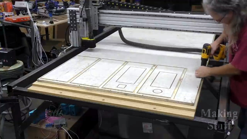
Many of us have spent the better part of a year on COVID-19 lockdown, and what do we have to show for it? Bit of progress on the Netflix queue? Maybe a (slightly) cleaned up garage or workshop? Not if you’re [Bob] of Making Stuff fame: he’s spent the last nine months working on a completely custom CNC router big enough to take a whole sheet of plywood.
The build is documented over a series of nearly a dozen YouTube videos, the first of which was put out all the way back in January of 2020. Seeing [Bob] heading to the steel mill to get his frame components with nary a mask in sight is a reminder of just how long he’s been working on this project. He’s also put together a comprehensive Bill of Materials on his website should anyone want to follow in his footsteps. Coming in at only slightly less than $4,000 USD, it’s certainly not a budget build. But then when we’re talking about a machine of this scale, nothing comes cheap.
Even if you don’t build you own version of this router, it’s impossible to watch the build log and not get inspired about the possibilities of such a machine. In the last video we’re even treated to a bit of self-replicating action, as the jumbo CNC cuts out the pieces for its own electronics enclosure.
You can tell from the videos that [Bob] is (rightfully) proud of his creation, and isn’t shy about showing the viewer each and every triumph along the way. Even when things don’t go according to plan, there are lessons to be learned as he explains the problems and how they were ultimately resolved.
Of course, we know a home-built CNC router doesn’t need to cost thousands of dollars or take up as much space as a pool table. The average Hackaday reader probably has no need of a monster like this, and wouldn’t have anywhere to keep it even if they did. But that doesn’t mean we can’t look on with envy as we wait to see what kind of projects [Bob] churns out with such an incredible tool in his arsenal.


4k for a router this size, it´s a bargain. It´s even too cheap, the frame does not look THAT sturdy
Those legs sure need diagonal bracing. That puppy with wiggle all over the place. Easy enough to fix, though.
Bolt plywood to 3 sides and you can still use all the space underneath? And take it apart if needed.
I never, once in my life, ever thought anything made with wooden parts was in any way ever “heavy duty”.
Straight open legs like that is craziness. No. Fix it by welding crossbraces between the legs and across the base of the table. Otherwise this will flex like a fish.
I swear- I’m really not trying to be mean, this is just straightforward design basics. You need stiffness and mass to machine with a large gantry router well. Wood will warp with humidity and temperature, it’s not a suitable material for components on a large machine expected of precision.
You covered it well.
He should cut those wood parts out of aluminum instead.
Steel is even better.
Clearly a machine that could be fixed easily to actually be good but still maybe now “heavy duty”.
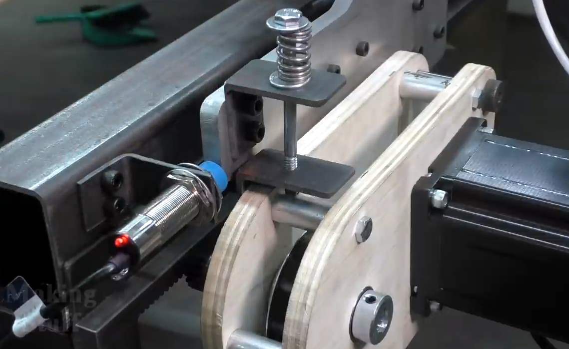
it is just the stepper drive it isn’t really structural
Plywood is les of a problem than bulk wood though.
Also you can boil wood in oil or wax to improve resistance to changes in humidity.
Totally agree on the legs though, the machine probably has a massive resonance peak that coincides with reasonable operating speeds.
He added croosbraces later on.
I can get 1.2x24m sheets of 45mm triboard that are actually flat to 1mm. That’s a lot better than random sheets of metal. It has it’s limits but wood is light, very stiff (because the beams can be big), can be quite well damped. It’s cheap. It doesn’t warp after welding. It’s easy to cnc and laser drill and cut. It doesn’t rust.
The grain linear CTE is _much_ better than aluminium and steel and on par with glass. https://www.engineeringtoolbox.com/linear-expansion-coefficients-d_95.html
Which is probably why you can putty a window into a wooden frame, but it has to be free floating in rubber in aluminium joinery.
I’ve built a similar CNC about 1/3 the size for approx $500. Works great on timber and 6mm acrylic sheet.
Probably would stuggle with metal, however that’s not what I built it for.
Take a look at Maslow. It is a vertical CNC controlled router kit. Will cut a full sheet of plywood (or whatever). Takes up less space. Costs about US$1000 (give or take).
Are you using one? The Maslow kinematics are attractive but suffer from some fatal flaws – like how do you get much pressure when “plunging”.
Yes, I built one. They work, and they work very well. They don’t have any “fatal flaws”, otherwise no-one would build one.
There is plenty of weight in the ‘sled’, which is the plywood or MDF disc that supports the router. This has two heavy weights attached, and the angle of the cutting board (about 15°) is sufficient to apply enough perpendicular force to cut.
I like my Maslow, but I spend as much time working on it as I do using it.
You’re doing it wrong. I built mine, calibrated it, and now I just use it.
Maybe your luck is better than mine, but my experience is that the Maslow is a very sensitive contraption.
I enjoy tinkering with it, but it sure can tell when you’re in a hurry.
Ah, yes. The only thing I might concur with is that Maslow puts the ‘slow’ in CNC routing. But, it’s cheap and capable.
I can see room for improvement too, as does he, such as using the machine to cut the electronics box. Once built, it can be improved on, using parts it can make. Like every project, one step at a time, but it’s finished, when it does what he wants. No need to overbroad if it fits the requirements of the builder. It’s nice being able to watch others, preferably many others, before I build something like this, to gain new ideas, inspiration, motivation, and help avoid learning things the hard way.
Not so much to copy, but to improve the tools available, to be creative.
Not so much what we have, but what we do with it.
He spent so much on that router that he can’t even afford a haircut.
The guy is doing cargo cult precision for his engineering. A steel beam supported at the ends will sag in the middle anyways, and it will sag differently depending on how the ends are supported so checking the amount in one case doesn’t apply to the other. The same thing goes for the string: you cannot pull it tight enough that it would not sag. Likewise, aligning the frame to within a “playing card” on the floor before welding, will not be the same after welding because the welds will pull it off, and when the frame is moved and a different load is placed on it, the stresses will change and his carefully adjusted plane goes all over the place.
So he does all this fiddling for nothing. If he really wants it anywhere straight, he has to add some means to pre-stress the structure against the load and force it straight after it’s been assembled. Otherwise all his measurements will change four times over the build process.
A simplified case for a beam suspended between two points that are free to pivot:
y = ( 5*m*g*L^3 ) / ( 384*E*I)
m and I you can find in your steel supplier’s catalog for the beam, and E for steel is 210 GPa. Take a typical 40x40x4mm tube: 4.2 kg/m with I = 1.25952e-7 m^4 in the base unit.
For an 8 ft beam (2438 mm) the result comes out as 7e-4 meters or 0.7 mm (27 thou) which is how much the beam will sag just by its own weight. Attempting to measure how “straight” it is with a feeler gauge while it’s bowing down anyways is an exercise in pointlessness.
How you fix the straightness issue: weld the ends of the beam shut and drill two holes off the center at the bottom. Insert a long threaded rod through the holes all the way through and start tightening it. This will pre-stress the beam against gravity and bend it back up. Of course any load you place on the beam will them make it sag again because you’ve only canceled the weight of the beam, not any additional loads. When the gantry rolls over the beam, it will still bend down as it will.
More to the point: assume that the string is tight enough to be “straight”, and the guy finds he has a 4 thou gap (0.1 mm), what can we deduce? We now know that the beam should be bent by 0.7mm but it isn’t, so it must already be bowed by 0.6 mm and he happens to have it facing up the way it has been bent like the arch of a bridge. The beam is not straight, he just got lucky. If he flips it around, it will bow down by 0.7 + 0.6 mm = 1.3 mm.
This is why you don’t trust your materials. Either you design the mechanism so it can be made level after assembly, or you design the machine so that it must be level regardless. For example, a laser shining into a light detector to follow the beam and correct the Z axis offset continuously.
As for the string:
https://www.engineeringtoolbox.com/cable-loads-d_1816.html
In order to have the string sag by no more than 0.01 mm in the middle, which we’ll call “straight” because it’s less than what you can reasonably measure, assuming it weighs 1 grams per meter, you have to hang a 7.2 kilo weight from the end to pull it. If it’s a thicker string that weighs 2 grams per meter, then you need 14.4 kilos etc.
It’s impossible to pull the string absolutely straight, because the leverage you get when the string is a perfect line is infinite. It takes exactly zero force to offset and sag it, so you can only approach a straight line. The only question then is, will your string take the pull?
0.01mm is not realistic for a gantry of that size though, let alone necessary for wood. To put into context, a laboratory AA grade 8’x4′ surface plate has a flatness tolerance of 0.0127mm. Even if you spent over $11000 to buy a 3000+Kg, 16″ thick slab of pink granite, and whatever it cost to install it into your thermally conditioned garage, you still couldn’t make your gantry that flat.
Woodworkers rarely work tolerances below 5 thou, and their tightest tolerances are needed for joinery, especially visible face joins.
Even if his gantry were perfectly flat, his floor is not. Increasing beam thickness, decreasing beam length (more legs perhaps), bracing for stiffness and including adjustable feet are practical measures to improvement. Keeping it flat during welding (or grinding it back flat) are also challenges that may need to be solved to achieve required tolerances.
Yeah, that’s just what you can’t reasonably measure anymore so it’s as good as “straight” in this case. After all, your standard must be better than what you’re measuring with it.
That said, he did the sensible thing and put the rails on the side where they can be adjusted, so ultimately it doesn’t matter that the top of the frame isn’t exactly straight. It just means the fine tuning and adjustment in the beginning was for naught.
The difficulty there is that the beam will have a bow to it sideways as well, so now the problem just shifted to another axis and hoping that the linear bearings won’t jam. As it so happens that both sides are bowed the same way, how to deal with having a banana-shaped track for the gantry? Well, again, you have to tension the frame somehow to take the curvature out, but first you have to figure out a way to measure it.
Otherwise, if you mill out some large object on it, that too will come out bent.