Given an unknown PCBA with an ARM processor, odds are good that it will have either the standard 10 pin 0.05″ or 20 pin 0.1″ debug connector. This uncommon commonality is a boon for an exploring hacker, but when designing a board such headers require board space in the design and more components to be installed to plug in. The literally-named Debug Edge standard is a new libre attempt to remedy this inconvenience.
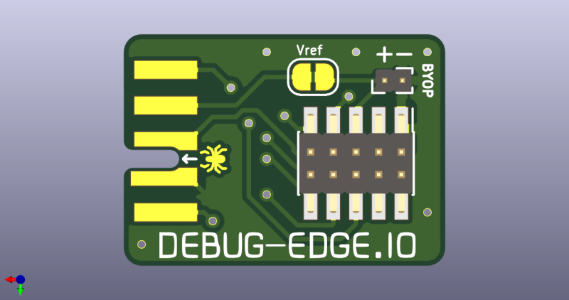
 The name “Debug Edge” says it all. It’s a debug, edge connector. A connector for the edge of a PCBA to break out debug signals. Card edge connectors are nothing new but they typically either slot one PCBA perpendicularly into another (as in a PCI card) or hold them in parallel (as in a mini PCIe card or an m.2 SSD). The DebugEdge connector is more like a PCBA butt splice.
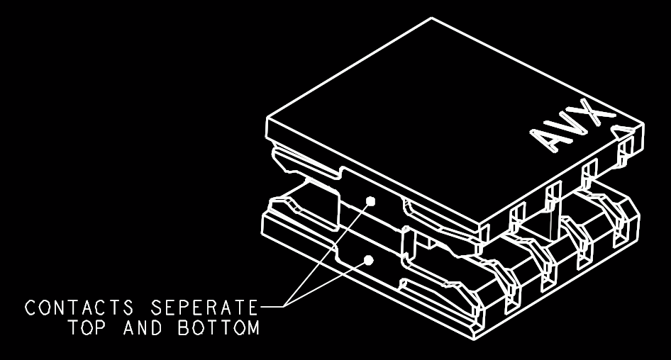
It makes use of a specific family of AVX open ended card edge connectors designed to splice together long rectangular PCBAs used for lighting end to end. These are available in single quantities starting as low as $0.85 (part number for the design shown here is 009159010061916). The vision of the DebugEdge standard is that this connector is exposed along the edge of the target device, then “spliced” into the debug connector for target power and debug.
Right now the DebugEdge exists primarily as a standard, a set of KiCAD footprints, and prototype adapter boards on OSHPark (debugger side, target side). A device making use of it would integrate the target side and the developer would use the debugger side to connect. The standard specifies 4, 6, 8, and 10 pin varieties (mapping to sizes of available connector, the ‘010’ in the number above specifies pincount) offering increasing levels of connectivity up to a complete 1:1 mapping of the standard 10 pin ARM connector. Keep in mind the connectors are double sided, so the 4 pin version is a miniscule 4mm x 4.5mm! We’re excited to see that worm its way into a tiny project or two.
We’ve seen plenty of part-free debug and programming connectors before. Have a favorite? Let us know in the comments!


I use a 3 pin SWD interface. SWDIO, SWCLK and GND, usually on 0.1″.
“such headers require board space in the design and more components to be installed to plug in.”
Ehmm… I don’t want to spoil the fun, but the problem with an edge connector is that the need to be on the edge of the board. And there need to go wires to that location, this takes up board space too.
Other than that, I love edge connectors simply because you get one (or more) “connectors” free with every board. Although, you should choose you board finish carefully if the connector is to be used somewhere in the far future when the PCB has gotten time to age and not every board finish ages well.
I’m pretty sure that this new concept grows into another standard. And then somebody else improves upon that and we have another incompatible standard and it goes on and on. But the thing I like the most about edge connectors, is that they have plenty of room for soldering wires.
>I’m pretty sure that this new concept grows into another standard. And then somebody else improves upon that and we have another incompatible standard and it goes on and on.
obligatory xkcd: https://xkcd.com/927/
I agree with problems of routing to the edge. I like the https://www.tag-connect.com/ variant better, another standard…
For those that can afford to route to the edge but can’t afford to waste board area, Tag-Connect also has a probe that connects to a set of castellated pads on the edge of the target board. I’ve been tempted to try it, because I don’t always have room for even their tiny standard pogo pin assembly. Somewhat pricey but I guess you only have to buy it once.
Woah, very cool, I haven’t seen that before! Cool use of little spring contacts.
I have used the Tag-Conect debug interface on a work project. It’s a $30 cable that does not lock onto the board very well. Even with their special clips, it kept coming loose.
Castellated pads may add a cost to your board.
And another problem is that edge connectors are quite difficult to access once the PCB is in an enclosure. TagConnect is similarly “free” on the board, and can be accessed in an enclosure also. But it is expensive and proprietary, no-legs version doesn’t stay in place well, and the legged version is huge.
A subject near and dear to my heart. In particular, I keep looking for a fast programming interface that allows me to program boards on small production run Just straight pogo pins seem like the cheapest and most flexible approach but it requires a special set up for each board type to ensure pin alignment. Tag connect looks ok but you have to dedicate board space to the mating holes and that can be just as much a pita as finding edge space.
Wish I could edit my comments.
Where the heck can you buy these things? Mouser appears to be clueless, Digikey has zero but a min order of 3000. No place else seems to know what it is. It’s great that people are thinking about this kind of stuff but if you can get the connector, why bother???
https://debug-edge.io has Octopart links for each width. Mouser has two of the 10 pin and Newark has a bunch. Digi-Key has a bunch of the 8 pin: https://www.digikey.com/short/zv81wr
Mouser will sell 1 at a time, $0.85 ea.
https://www.mouser.com/ProductDetail/AVX/009159010061916?qs=KyAyYtce1XNwmb0BBopbmw%3D%3D
5,000 coming at the end of the year.
Newark will sell 1 at a time for $0.76 ea.
https://www.newark.com/avx-interconnect/009159010061916/card-edge-conn-dual-side-10pos/dp/85W8864
2,747 In stock
I’ve used SOICbite (https://hackaday.com/2019/06/13/soicbite-a-program-debug-connector-for-an-soic-test-clip/) for a temporary debug connection and its worked well. You do need to modify the clip though.
Yes! I’m a big fan of SOICbite too
That huge clip isn’t going to work well inside an enclosure.
The board to board connector can be found at RS components with ID 174-4977 (£0.513 per 200 pcs). 370 pcs in stock
IMHO, there is not a single solution that fits all needs between cost (connector, board space), quantities, debugging or batch programming, etc…
AVX10 connector pros and cons seems to be:
+ No connector (cost) required on target board side (=Tagconnect)
+ cheaper solution than using 10 pin 0.05″ header and ribbon or $40 Tagconnect (which is for large batch programming)
+ no holes/via, better signal integrity
+ can manually solder 2mm pitch header or DF11 connector on the PCB edge with this footprint (https://uk.rs-online.com/web/p/pcb-headers/1665026/ )
+ firm grip compared to SOICbite
+ scalable, when requirering more signals, can add more BTB aside to get 20, 30, 40 signals.
– requires standard PCB thickness
– connector wear and tear (probably not designed for 1000s insertion, unless it is hand mofified to be a miniature version of the SOICbite… that would only require smaller case opening
– single source, although mitigated by standard 2mm pitch, various cheap headers can be soldered on the PCB edge like SMA RF connectors
Also the PCB footprint is pogo friendly if vital signals are placed on one PCB side like SWDIO, SWDCLK, GND
High volume production usually would probabaly use either tag connect or custom pogo board.
I use the WR-WST REDFIT IDC SKEDD (https://www.we-online.de/katalog/en/em/REDFIT_IDC_SKEDD). It doesn’t need an extra adapter PCB for my programmer. It clips on the existing ribbon-cable of my programmer. It doesn’t have the limitations of an edge connector. I can place the footprint anywhere on my PCB, where it’s still available once the PCB is mounted in a housing. For higher volume series, the same footprint can be used by a bed-of-nails fixture, which would only require probing pins on bottom side of the PCB.
I had this same idea with some ATMEGA328p boards I designed for a makerspace class. The board had a card-edge breakout of the SPI programming header and the ICE/ISP had an intermediate board it plugged into which broke out the pins into the card-edge connector. The beauty of this was that the kits could be programmed very quickly in-class in a toaster like fashion but when the kids took them home, a 2×3 through-hole header could be soldered on to the board edge and the thing could be programmed like a regular arduino (sans FTDI chip).
It is novel, but not practical at all. With the right board thickness you could even just cram a 0.1″ header on the board edge instead of an edge connector. The TagConnect solves the same problem, but with actual space savings. I really don’t see what adding yet another standard would benefit.
I’ve been quite successful using holes for 0.05″ header, with slightly bigger spacing, so that a male 0.05 connector locks into them. It takes very little space, requires no specialized cable and no PCB to be printed. I typically put it in the corner of the board, but it can be also in the middle.
Previously, I would use 0.1″ header holes at exactly 0.1″ from the edge, which makes a 2-row male header lock into them.
See here https://arcade.makecode.com/hardware/dbg
This is great! I’ve almost came up with my own “standard” for my own projects..
The only problem is that most of my projects are Arduino based, therefore I use the SPI (MISO, MOSI) 2×3 header that I’d like to replace with this standard… That unfortunately doesn’t support SPI.