Open Hardware GPS Tracker Works On Your Terms

These days, there’s plenty of options if you want to get a GPS tracker for your vehicle. Unfortunately, they come with the sort of baggage that’s becoming increasingly common with consumer tech: subscription fees, third-party snooping, and a sneaking suspicion that you’re more commodity than customer. So [Viktor Takacs] decided to take things into his own hands and create an open GPS tracker designed for privacy minded hackers.

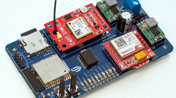
As [Viktor] didn’t want to reinvent the wheel, his design leverages several off-the-shelf modules. The core of the tracker is the ESP32, which gives him plenty of computational power while still keeping energy consumption within reasonable levels. There’s also a NEO-6M GPS receiver which works at the same 3.3 V level as the ESP32, allowing the microcontroller to read the NMEA sentences without a level shifter. He decided to go with the low-cost SIM800L GSM modem, but as it only works on 2G networks, provisions have been made in the board design to swap it out for a more modern module should you desire.

For the code to glue it all together, [Viktor] pulled in nearly a dozen open source libraries to create a feature-complete firmware that uses MQTT to create a database of location data on his personal server. From there the data is plugged into Home Assistant and visualized with Grafana. This is enough to deliver core functionality, but he says that more custom software components as well as a deep-dive into the security implications of the system is coming in the near future.

We’ve seen custom built GPS trackers before, as generally speaking, it doesn’t take a whole lot to spin up your own solution. But we think the polish that [Viktor] has put on this project takes it to the next level, and ranks it up there among some of the most impressive bespoke tracking solutions we’ve seen over the years.

Ham Radio Needs To Embrace The Hacker Community Now More Than Ever

As many a radio amateur will tell you, ham radio is a hobby with as many facets as there are radio amateurs. It should be an exciting and dynamic place to be, but as those who venture forth into it sometimes sadly find out, it can be anything but. Tightly-knit communities whose interests lie in using $1,000 stations to chase DX (long-distance contacts), an advancing age profile, and a curious fascination of many amateurs with disaster communications. It’s something [Robert V. Bolton, KJ7NZL] has sounded off about in an open letter to the amateur radio community entitled “Ham Radio Needs To Embrace The Hacker Community Now More Than Ever“.

In it he laments that the influx in particular of those for whom disaster preparedness is the reason for getting a licence is to blame for amateur radio losing its spark, and he proposes that the hobby should respond by broadening its appeal in the direction of the hacker community. The emphasis should move from emergency communications, he says, and instead topics such as software defined radio and digital modes should be brought to the fore. Finally he talks about setting up hacker specific amateur radio discussion channels, to provide a space in which the talk is tailored to our community.

Given our experience of the amateur radio community we’d be bound to agree with him. The hobby offers unrivalled opportunity for analogue, mixed-signal, digital, and software tinkering in the finest tradition of the path set by the early radio amateurs around a hundred years ago, yet it sometimes seems to have lost its way for people like us. It’s something put into words a few years ago by our colleague Dan Maloney, and if you’re following [KJ7NZL]’s path you could do worse than read Dan’s long-running $50 ham series from the start.

Via Hacker News.

Header image: Unknown author, Public domain.

Taking Over The Amazing Control Panel Of A Vintage Video Switcher

Where does he get such wonderful toys? [Glenn] snagged parts of a Grass Valley Kalypso 4-M/E video mixer switcher control surface from eBay and since been reverse engineering the button and display modules to bend them to his will. The hardware dates back to the turn of the century and the two modules would have been laid out with up to a few dozen others to complete a video mixing switcher console.

[Glenn’s] previous adventures delved into a strip of ten backlit buttons and gives us a close look at each of the keyswitches and the technique he used to pull together his own pinout and schematic of that strip. But things get a lot hairier this time around. The long strip seen above is a “machine control plane” module and includes a dozen addressible character displays, driven by a combination of microcontrollers and FPGAs. The square panel is a “Crosspoint Switch Matrix” module include eight individual 32 x 32 LCDs drive by three dedicated ICs that can display in red, green, or amber.

[Glen] used an STM8 Nucleo 64 to interface with the panels and wrote a bit of code to help map out what each pin on each machine control plane connector might do. He was able to stream out some packets from the plane that changed as he pressed buttons, and ended up feeding back a brute-force of that packet format to figure out the LED display protocols.

But the LCDs on the crosspoint switch were a more difficult nut to crack. He ended up going back to the original source of the equipment (eBay) to get a working control unit that he could sniff. He laid out a man-in-the-middle board that has a connector on either side with a pin header in the middle for his logic analyzer. As with most LCDs, the secret sauce was the initialization sequence — an almost impossible thing to brute force, yet exceedingly simple to sniff when you have a working system. So far he has them running under USB control, and if you are lucky enough to have some of this gear in your parts box, [Glen] has painstakingly recorded all of the details you need to get them up and running.

Scratch Building A Supersized CNC Router

Many of us have spent the better part of a year on COVID-19 lockdown, and what do we have to show for it? Bit of progress on the Netflix queue? Maybe a (slightly) cleaned up garage or workshop? Not if you’re [Bob] of Making Stuff fame: he’s spent the last nine months working on a completely custom CNC router big enough to take a whole sheet of plywood.

The build is documented over a series of nearly a dozen YouTube videos, the first of which was put out all the way back in January of 2020. Seeing [Bob] heading to the steel mill to get his frame components with nary a mask in sight is a reminder of just how long he’s been working on this project. He’s also put together a comprehensive Bill of Materials on his website should anyone want to follow in his footsteps. Coming in at only slightly less than $4,000 USD, it’s certainly not a budget build. But then when we’re talking about a machine of this scale, nothing comes cheap.

Every component on this build is heavy-duty.

Even if you don’t build you own version of this router, it’s impossible to watch the build log and not get inspired about the possibilities of such a machine. In the last video we’re even treated to a bit of self-replicating action, as the jumbo CNC cuts out the pieces for its own electronics enclosure.

You can tell from the videos that [Bob] is (rightfully) proud of his creation, and isn’t shy about showing the viewer each and every triumph along the way. Even when things don’t go according to plan, there are lessons to be learned as he explains the problems and how they were ultimately resolved.

Of course, we know a home-built CNC router doesn’t need to cost thousands of dollars or take up as much space as a pool table. The average Hackaday reader probably has no need of a monster like this, and wouldn’t have anywhere to keep it even if they did. But that doesn’t mean we can’t look on with envy as we wait to see what kind of projects [Bob] churns out with such an incredible tool in his arsenal.

Continue reading “Scratch Building A Supersized CNC Router”

This Debug Connector Brings Your Issues To The Edge

Given an unknown PCBA with an ARM processor, odds are good that it will have either the standard 10 pin 0.05″ or 20 pin 0.1″ debug connector. This uncommon commonality is a boon for an exploring hacker, but when designing a board such headers require board space in the design and more components to be installed to plug in. The literally-named Debug Edge standard is a new libre attempt to remedy this inconvenience.

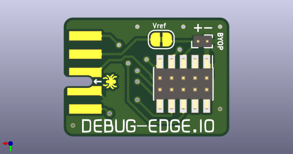
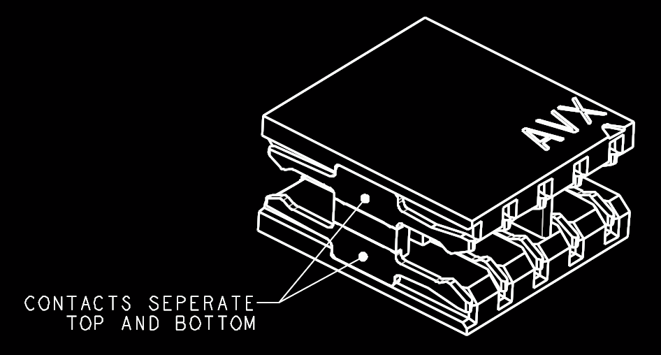
The name “Debug Edge” says it all. It’s a debug, edge connector. A connector for the edge of a PCBA to break out debug signals. Card edge connectors are nothing new but they typically either slot one PCBA perpendicularly into another (as in a PCI card) or hold them in parallel (as in a mini PCIe card or an m.2 SSD). The DebugEdge connector is more like a PCBA butt splice.

It makes use of a specific family of AVX open ended card edge connectors designed to splice together long rectangular PCBAs used for lighting end to end. These are available in single quantities starting as low as $0.85 (part number for the design shown here is 009159010061916). The vision of the DebugEdge standard is that this connector is exposed along the edge of the target device, then “spliced” into the debug connector for target power and debug.

Right now the DebugEdge exists primarily as a standard, a set of KiCAD footprints, and prototype adapter boards on OSHPark (debugger side, target side). A device making use of it would integrate the target side and the developer would use the debugger side to connect. The standard specifies 4, 6, 8, and 10 pin varieties (mapping to sizes of available connector, the ‘010’ in the number above specifies pincount) offering increasing levels of connectivity up to a complete 1:1 mapping of the standard 10 pin ARM connector. Keep in mind the connectors are double sided, so the 4 pin version is a miniscule 4mm x 4.5mm! We’re excited to see that worm its way into a tiny project or two.

We’ve seen plenty of part-free debug and programming connectors before. Have a favorite? Let us know in the comments!

Sims-Style Plumb Bob Broadcasts Your Mood

While there are a lot of objects from the Sims that we wish were real, we probably wish more than anything that everyone had a mood indicator hovering above their heads at all times. It would make working from home go a lot more smoothly, for instance. [8BitsAndAByte] made this Bluetooth-controlled plumb bob as part of their Sims Halloween costume, but we think it has real day-to-day value as this pandemic wears on, either as a mood ring or a portable free/busy indicator.

The hardware is about as simple as it gets — an Adafruit Feather nRF52 Bluefruit controls a pair of NeoPixel rings, one for each half of the translucent 3D-printed plumb bob. Power comes from a 500mAh battery, and all the electronics are situated inside of an attractive hat. Check out the build video after the break.

There’s more than one way to use color to convey information. This seven-segment temperature display does it with thermochromic film.

Continue reading “Sims-Style Plumb Bob Broadcasts Your Mood”

TMD-2: A Bigger, Better, More Collaborative Turing Machine

One of the things we love best about the articles we publish on Hackaday is the dynamic that can develop between the hacker and the readers. At its best, the comment section of an article can be a model of collaborative effort, with readers’ ideas and suggestions making their way into version 2.0 of a build.

This collegial dynamic is very much on display with TMD-2, [Michael Gardi]’s latest iteration of his Turing machine demonstrator. We covered the original TMD-1 back in late summer, the idea of which was to serve as a physical embodiment of the Turing machine concept. Briefly, the TMD-1 represented the key “tape and head” concepts of the Turing machine with a console of servo-controlled flip tiles, the state of which was controlled by a three-state, three-symbol finite state machine.

TMD-1

TMD-1 was capable of simple programs that really demonstrated the principles of Turing machines, and it really seemed to catch on with readers. Based on the comments of one reader, [Newspaperman5], [Mike] started thinking bigger and better for TMD-2. He expanded the finite state machine to six states and six symbols, which meant coming up with something more scalable than the Hall-effect sensors and magnetic tiles of TMD-1.

TMD-2 has a camera for computer vision of the state machine tiles

[Mike] opted for optical character recognition using a Raspberry Pi cam along with Open CV and the Tesseract OCR engine. The original servo-driven tape didn’t scale well either, so that was replaced by a virtual tape displayed on a 7″ LCD display. The best part of the original, the tile-based FSM, was expanded but kept that tactile programming experience.

Hats off to [Mike] for tackling a project with so many technologies that were previously new to him, and for pulling off another great build. And kudos to [Newspaperman5] for the great suggestions that spurred him on.