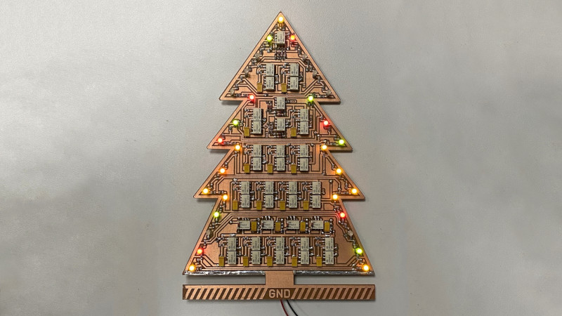
There are a great variety of ways to build a random number generator, and similarly many ways to generate numbers that appear random, but in a pure mathematical sense generally aren’t. [Daniel Valuch] built a Christmas decoration that does the latter, displaying the results on an attractive flashing ornament.
The build relies on a 16-bit linear feedback shift register, or LFSR. The LFSR generates a stream of numbers, with each number dependent on the previous state of the register. Thus, the numbers generated are pseudorandom, not truly random, and depend on the initial seed value of the system. [Daniel] built the shift register using relays, which create a lovely clacking sound as the register operates, and LEDs, which glow depending on the values in the register.
The result is a cute Christmas ornament that blinks in a deterministic fashion, and has a great old-school look due to the exposed copper of the PCB and the retro LED colors used. The project also serves as a great way to learn about shift registers and basic relay logic, though the latter is rarely used these days for serious purposes. We’ve covered the topic before, too. Video after the break.


You probably meant to link to this video: https://www.youtube.com/watch?v=6Pp9ys1MGVs
The numbers displayed in the linked video are clearly not quite random ;)
it’s pseudo-random, as the title explains :-)
As always, a related XKCD:
https://xkcd.com/221/
Well, there are 4 videos in the playlist. Testing, which is not random, and then the full run, which is pseudo-random :-) The sequence length, before it repeats is 18 hours and a bit.
Do you have a page or logs that describe the circuit and its design ?
Hi, here is the schematic http://dvaluch.web.cern.ch/temp/LFSR_relay.pdf
Interesting circuit.
I am trying to figure out the operation, and have started with the clock generation part. Can anyone help me understand the operation of the K37. K38, K40 part of this circuit? I think that K40 isn’t getting switched, so I guess I am looking at this wrong.
I’m amused by the fact the ground is depicted as ground on the PCB, possibly slightly too amused at the moment. Although saying that, the optics part of my physics brain is also saying mirror, it’s been a while since I’ve had to use the old symbols for ground.
I wonder if reliably chaotic behavior is possible with relays? Race conditions probably aren’t enough, since some relays will probably be consistently faster than others.
But what if you use the LFSR state to drive a resistor ladder pseudo-DAC that controls current to another relay, which randomly inverts bits of the internal state?
The exact activation voltage will probably have hysteresis and act as an extra bit of memory, in addition to maybe being temperature sensitive.
You could also have a free-running oscillator somewhere.
Yes, it has hysteresis (pull in voltage usually at least 2 times the drop out), but that’s not memory. Of course the voltages are temperature dependent, at least by the tempco of the copper wire’s resistance.