PentaBlinky – When One LED Is Not Blinky Enough

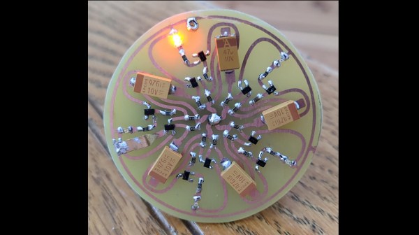
[michimartini] over on Hackaday.io loves playing with multivibrator circuits, and has come across a simple example of a ring oscillator. This is a discrete transistor RC-delay design utilizing five identical stages, each of which has a transistor that deals with charging and discharging the timing capacitor, passing along the inverted signal to its nearest neighbor. The second transistor isn’t strictly needed and is only there to invert the signal in order to drive the LED. When the low pulse passes by the LED lights, without it you’d see all the LEDs lit bar one, which doesn’t look as good.

Compare this with an astable multivibrator to understand how it works

Essentially this circuit is just the classic astable multivibrator circuit that has been split in half and replicated so that the low pulse propagates through more stages than just the two, but thinking about it as a single stage doesn’t work so well until you draw in a couple of neighbors to help visualize the behavior better.

[michimartini] does lament that the circuit starts up in a chaotic fashion and needs a quick short applying to one transistor element in order to get it to settle into a steady rhythm. Actually, that initial behaviour could be interesting in itself, especially as the timing changes with voltage and temperature.

Anyway, we like the visual effect and the curvy organic traces. It would make a neat pin badge. Since we’re thinking about blinkies, here are couple of somewhat minimalist attempts, the world’s smallest blinky, and an even smaller one. Now, who doesn’t love this stuff?

Continue reading “PentaBlinky – When One LED Is Not Blinky Enough”

A Relay-Based Pseudorandom Number Generator

There are a great variety of ways to build a random number generator, and similarly many ways to generate numbers that appear random, but in a pure mathematical sense generally aren’t. [Daniel Valuch] built a Christmas decoration that does the latter, displaying the results on an attractive flashing ornament.

The build relies on a 16-bit linear feedback shift register, or LFSR. The LFSR generates a stream of numbers, with each number dependent on the previous state of the register. Thus, the numbers generated are pseudorandom, not truly random, and depend on the initial seed value of the system. [Daniel] built the shift register using relays, which create a lovely clacking sound as the register operates, and LEDs, which glow depending on the values in the register.

The result is a cute Christmas ornament that blinks in a deterministic fashion, and has a great old-school look due to the exposed copper of the PCB and the retro LED colors used. The project also serves as a great way to learn about shift registers and basic relay logic, though the latter is rarely used these days for serious purposes. We’ve covered the topic before, too. Video after the break.

Continue reading “A Relay-Based Pseudorandom Number Generator”

A Wedding Gift Fit For A Hardware Hacker

If you read Hackaday on a regular basis, there are some names you will have seen more than once. People who continually produce fascinating and inventive projects that amaze and delight us, and who always keep us coming back for more. One such hacker is [Jeroen Domburg], perhaps better known in these pages by the handle [Sprite_TM], who has never failed to delight us in this respect.

Today is a special day for [Jeroen] for it is his wedding day, and his friend [Maarten Tromp] has decided to surprise him and his wife [Mingming] with a special gift. At first sight it is simply a pair of blinky badges in the shape of a bride and groom, but closer examination reveals much more. The PCBs are studded with WS2812 addressable LEDs controlled by an ESP32 module and powered by a small LiPo battery, and the clever part lies in the software. The two badges communicate via Bluetooth, allowing them to both synchronise their flashing and flash ever faster as the couple come closer to each other.

The write-up is an interesting tale of the tribulations of designing a badge, from which we take away that buying cheap LEDs may be a false economy. A surprise was that the black-cased and white-cased versions of the LEDs had different timings, and they proved prone to failure.

We wish the happy couple all the best, thank [Sprite_TM] for all he has given us over the years, and look forward to seeing his future projects.

An Even Smaller World’s Smallest LED Blinky

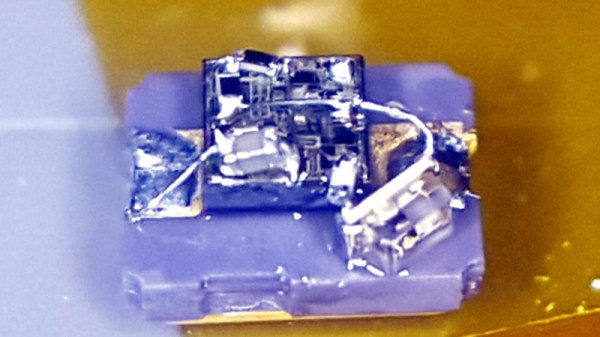
Everything can be done with a 555. It’s a universal law, as all readers know. And a flashing light, you might think, will have been done before many times. But nobody has ever created a 555 flashing light as small as thie one created by [TWires], who has taken a TI LMC555 chip-scale packaged 555 and dead-bugged a working flasher on its surface using 01005 discrete components. There is a video showing it in operation that we’ve placed below the break, and it’s tiny. We probably all consider ourselves to be quite good at soldering, but this piece of work is in another class entirely.

The project was inspired by [Mike Harrison]’s previous holder of the smallest blinky prize, which used a PIC microcontroller atop a tiny surface mount supercapacitor. It uses the same capacitor for power, but we’d say it’s taken the blinky to new levels of tininess. Does this mean a new arms race is upon us in the world of tiny blinkies? We hope so, and though it’s difficult to imagine they can get much smaller we can’t wait to see what people come up with. If there’s one thing about our community it’s that saying something can’t be done is unwise: one of you will find a way if it is at all possible. Even Microchip’s MIC1555 might be a bit big though, so something inventive is called for.

For a fascinating run-down of the state of the 555 art, read this article from our own [Ted Yapo].

Continue reading “An Even Smaller World’s Smallest LED Blinky”

Gyro Controlled RGB Blinky Ball Will Light Up Your Life

[James Bruton], from the XRobots YouTube channel is known for his multipart robot and cosplay builds. Occasionally, though, he creates a one-off build. Recently, he created a video showing how to build a LED ball that changes color depending on its movement.

The project is built around a series of 3D printed “arms” around a hollow core, each loaded with a strip of APA102 RGB LEDs. An Arduino Mega reads orientation data from an MPU6050 and changes the color of the LEDs based on that input. Two buttons attached to the Mega modify the way that the LEDs change color. The Mega, MPU6050, battery and power circuitry are mounted in the middle of the ball. The DotStar strips are stuck to the outside of the curved arms and the wiring goes from one end of the DotStar strip, up through the middle column of the ball to the top of the next arm. This means more complicated wiring but allows for easier programming of the LEDs.

Unlike [James’] other projects, this one is a quickie, but it works as a great introduction to programming DotStar LEDs with an Arduino, as well as using an accelerometer and gyro chip. The code and the CAD is up on Github if you want to create your own. [James] has had a few of his projects on the site before; check out his Open Dog project, but there’s also another blinky ball project as well.

Continue reading “Gyro Controlled RGB Blinky Ball Will Light Up Your Life”

World’s Smallest LED Blinky

[Mike Harrison] is known for incredibly tiny soldering. Now he’s claiming a “world’s smallest” in the form of a stand-alone LED blinker, and we think he’s got the record.

He brought it along with him to Friday’s Beagleboard Bring-a-Hack, and we got a close look at the diminutive assembly. The project was dreamed up when [Mike] saw an announcement from Seiko about a new supercapacitor in a tiny package (likely the CPH3225A giving the blinky a footprint of 3.2 x 2.5 mm). With that in hand he added a PIC 10f322 microcontroller in a SOT23 package, an 0603 smoothing capacitor, and an SMD LED.

With such a tiny package, the trickiest part is figuring out how to charge that supercap. [Mike] used a drill and hand files to make a square hole in a CR2032 battery holder to serve as a jig. The bottom of the supercap rests against the battery as a pogo pin makes the second connection to a terminal on the side of his assembly. It charges quickly and will happily blink away for about six minutes after charging.

Mike set out to make two of these, but dropped the second supercap when at his workbench to be forever lost in the detritus common to every electronics workshop. When he first pulled it out at the meetup we were on a rooftop terrace and we were more than a bit concerned that this would just blow away. How do you begin to fabricate such a tiny assembly? He used UV cured epoxy to glue them together first, then somehow completed the soldering by hand!

Continue reading “World’s Smallest LED Blinky”

Badgelife: From 1 To 100

Blame it on the falling costs of printed circuit boards, the increased accessibility of hardware design tools, the fact that GCC works on microcontrollers now, whatever the ‘maker movement’ is, or any one of a number of other factors. There’s a hardware demoscene now. Instead of poking bits, writing code, and dividing by zero to create impressive multimedia demonstrations on a computer, there is a small contingent of very creative people who are building their own physical hardware, just for the hell of it. They’re pushing boundaries of what can be done with hardware design, demonstrating manufacturing know-how, and turning a (small) profit while doing it. This is badgelife, the tiny subculture dedicated to creating custom electronic conference badges.

At Hackaday, we’ve been doing a deep dive into the rigors of this demoscene of hardware, and last week we had the pleasure of hosting a meetup with some of the big players of the badgelife community as guests of honor. There were, of course, talks discussing the trials and tribulations of designing, manufacturing, and shipping hundreds of pieces of hardware on a limited budget with not enough time. If you want to know how hard electronic design and manufacturing can be, you want to check out these talks below. Continue reading “Badgelife: From 1 To 100”