CNC machines made from wood and 3D-printed parts may be popular, but they aren’t always practical from a precision and repeatability standpoint. This is especially true as the machines are scaled up in size, where the compliance of their components starts to really add up. But can those issues be resolved? [jamie clarke] thinks so, and he’s in the process of building a CNC router that can handle a full sheet of plywood. (Video, embedded below.)
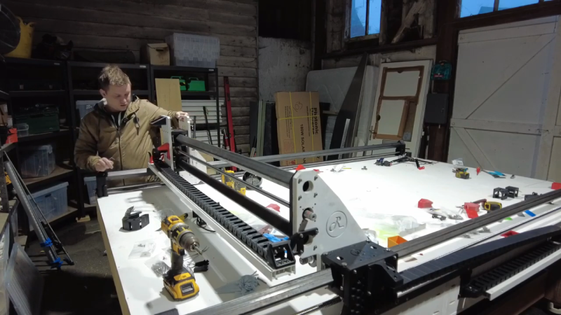
This is very much a work in progress, and the videos below are only the very beginning of the process. But we found [jamie]’s build interesting even at this early point because he has included a few clever tricks to control the normal sources of slop that plague larger CNC machines. To provide stiffness on a budget, [jamie] went with a wooden torsion-box design for the bed of his machine. It’s the approach taken by the Root CNC project, which is the inspiration for this build. The bed is formed from shallow boxes that achieve their stiffness through stressed skins applied to rigid, lightweight frames.
Upon the torsion-box bed are guide rails made from commodity lengths of square steel tubing. Stiff these may be over short lengths, but over the three meters needed to access a full sheet of plywood, even steel will bend. [jamie]’s solution is a support that moves along with the carriage, which halves the unsupported length of the beam at all points of travel. He’s using a similar approach to fight whip in the ball screw, with a clever flip-down cradle at the midpoint of the screw.
So far, we’re impressed by the quality of this build. We’re looking forward to seeing where this goes and how well the machine performs, so we’re paying close attention to the playlist for updates. At an estimated build cost of £1,500, this might be just the CNC build you’ve been looking for.


A standard solution for affordable commercial machines like that is flipping them upright and using two driver rods. Depth (Z-axis) rigidity is neglected for x-Axis rigidity, since on these formats it’s mostly just ‘cutting it out’ anyways.
Sigh, yet another bad example of building a relatively big CNC router.
I’ve seen a lot of them and underestimating the need for stiffness is by far the most common issue with them.
Building a torsion box is good, even if it’s just out of wood, but it is of not much use if you put those long unsupported rails on it.
First making those unsupported rails, and then adding those strips on the side later is also just a ad-hoc kludge that does not work sideways.
For a decent design, the long square tubes itself should have been integrated into the wooden torsion box.
And you can do a lot more with the torsion box Idea.
Take the gantry, and replace the two flimsy steel beams with a wooden torsion box of around 300x400mm. Even when made out of 6mm MDF it will be cheaper lighter and stiffer then the two steel beams. Then add just enough steel to make some rails to run some bearings over. Preferably cold rolled steel or anything harder then just mild steel.
Each and every professional CNC router of this size will have a hollow torsion box for the gantry. Take a good look at them, and make sure you understand why they are build the way they are before you make one yourself.
I don’t want to be bitchin’ or breaking down such projects, but I find it quite sad that a project that clearly takes a lot of time and effort to build (and some money) could have easily resulted in a much more useful end product if details like this were taken into account.
I put in some effort to find one that clarifies what I meant.
The link below has both a wooden torsion box for the table and gantry, and has the guidance for the Y axis mounted to the torsion box table itself.
The guidance rails itself are a bit flimsy, but that would just another small improvement to make.
https://www.youtube.com/watch?v=jjdXpp77MdU
Cheers Paul, jamie here. I appreciate your feedback and taking the time to post an example of what you mean.
I’ve got tons of comments about the unsupported rails and I’ve got an even better idea for a machine now which will have support rails and do away with the ball screws. Hint, it’s not even rack and pinion.
Hi Jamie
You can make things easier on yourself by leaving the screw static and spinning the nut. It means cable management, but you can essentially remove screw whip from the equation that way. You can even use the screw as a tension member.
Rack and pinion is one of the stiffest connections, and often used fort the bigger routers. The benefit is because the rack is mounted to the bed over it’s whole length, which makes it quite stiff. A long ball-screw gets stretched and compressed by longitudinal forces.
For a wood router, straight teeth are good enough, for better accuracy for example small letters in homogeneous plastic) the use of a helical pinion and slanted teeth is preferred.
Stationary belt or chain, looped between a drive pulley or sprocket and a pair of idlers?
Putting ballscrews under tension with angular contact bearings at the ends is a way to control whip.
i keep hoping to see one of these where they just accept that the whole thing flexes to heck, and they more than make up for it with closed-loop control.
i use my cheap fdm 3d printer a bunch but it still surprises me that anything gets any tolerable precision with open loop control. just send the number of pulses to the steppers and assume blindly that you know how far the head moved. crazy!
Where were you thinking they would close the loop? If done at the motor / shaft, surely it doesn’t address the flex in the frame. If the tool’s coordinates were read externally, maybe it would work?
I suppose the Shaper Origin would be an extreme example of this.
The best way I can think of to close the loop is a high-DPI optical flow sensor like a computer mouse. But it would be a LOT of work.
Hey Greg, jamie here, this machine has closed loop control I’m just configuring it now 👍
I realise this post is from a year ago, yet… It’s new to me. A CNC project from a while back “goodenoughcnc” came up with an interesting solution to the ‘open-loop’ feedback, and grounding issues with their “toslinkCNC” (http://goodenoughcnc.eu/other-projects/) concept where communication to the steppers was done using low cost fibre optic cables. Details are on github (https://github.com/IRNAS/ToslinkCNC).
May interest some of the CNC obsessed ;)
Super interested in this kinda thing but always get put off (from attempting it myself) by the fear of engaging in a never ending quest to solve zillions of problems I didn’t see coming – instead of actually using it as a tool. Bit like early 3D printers. The little ball screw flip up support contraptions are actually a pretty rad idea though. I have a couple of printers that use stainless box section as linear rails. Work reasonably well. Presume if you’re just looking to route large format stuff like full sheets of ply/MDF etc then slight variances in Z height from sagging rails would probably be tolerable.
Hey Dion, if you don’t need the full 8ft of travel this machine makes a super sturdy 4ft x 4ft and it’s pretty easy and cheap to build
The guy makes the error of assuming that doubling the tube dimensions doubles the area moment of inertia. Instead, the diagonal moment is relative to the fourth power of the width of the box section, so doubling the stiffness only needs an increase of 19% in linear dimensions, so from a 40 mm beam to 50mm would more than double the stiffness. See the “Parallel axis theorem” for more insight to why this happens.
Then, you can add a long threaded rod down the bottom corner of the box tube and tension the rod against the ends, which causes a bending moment along the beam, so the pre-stressing cancels the sag caused by its own masst. When the carriage moves along the rail, that causes a varying load which cannot be completely eliminated this way, but you can add some additional tension to reduce the error.
Awesome, good to know dude. I’ll take this into account for my next machine.
When you balance the tension on the beam with the weight of the carriage in the middle, the error is removed at both ends and in the middle, and instead of one large sagging parabola you get two smaller ones that lift the carriage up slightly at 1/4 and 3/4 along the beam. You can then fine-tune it further by easing the tension just a little bit, which makes the carriage sag in the middle again, but the two side humps drop down.
So instead of one big droop in the middle, the carriage makes a sort of sine wave that crosses the straight axis at four points: both ends and two in the middle, and the maximum deviation from a straight line is reduced to a fraction of the original.
If you’re starting from a millimeter of droop, your rails are simply not stiff enough, but if you’re already down to a reasonable stiffness and you want to improve the accuracy, that’s a good trick to remember: bend the beam from the ends and it will bow up in the middle.
I’m not high enough to follow that even sober.
But for some reason I believe you. You need a youtube channel.
The basic point: if you have a bar of material with a cross-section area A, it has a bending moment of inertia I around some crosswise axis of bending that depends on this area. Whichever axis you choose to bend it around has a different I. It resists bending around this axis by a factor of k = 48EI / L like shown in the video, which is a sort of spring constant of the beam system and depends on the configuration.
It’s not universal, but this formula is close to the case at hand. For the same case, you can calculate the actual sag in the middle by, y = FL^3 / 48EI. These are all prototype cases that were solved analytically and experimentally a hundred years ago, and can be found in an engineering tables book.
Now, the Parallel Axis Theorem states that when you take the area A and displace it some distance r away from your axis of bending, you not only get the original bending moment I but you have an additional term proportional to A*r^2. In other words, when you put your support further away from the pivot point, it has more leverage to resist the bending, and this happens to work out mathematically the same as rotational inertia, which is why it’s called the bending moment of inertia.
So, when you increase the dimensions of your box tube, you get the area term A proportional to the square of the thickness of the beam, but since the material is also moved away from the bending axis, you also get to multiply the area by the r^2 term, and so the stiffness of your box beam increases in the fourth power of its linear dimensions. This is crucial to machine design: instead of using heavy solid beams, you simply place the material further away from the axis of bending. That’s exactly what the torsion box table is doing as well.
That flip-down screw cradle mechanism looks potentially troublesome. If the carriage moves past it, but stops exactly just before the mechanism flips up, and then tries to reverse, it may jam. This depends upon the tolerances and the shape of the interacting edges. You either want to design it such that it can’t partially flip up, or such that if it does partially flip up, it will just go right back down when the carriage is reversed.
Ya what if he has part of his cad file that needs to be between those 2 extremes?
Also with regard to the long support beam stiffness: he adjusted his design to take care of the vertical loading of the carriage weight, but he didn’t consider any perpendicular loading that might result from the tool pushing on the stock. Probably this isn’t a big issue. But it seems like a better design would be to have C-shaped carriages that free up one side (one corner edge) of the rail, allowing that side to be attached to the machine along its length.
Once again, for low-cost, large area, DIY CNC work take a look at Maslow. Among its many advantages are that it is vertical and therefore takes minimal space.
Ignore the naysayers who haven’t actually built one (or even seen one, let alone used one).
Why the trouble to reinvent the wheel with the ball screw? Whiplash is a problem, which is exactly why it shouldn’t be direct drive, but rather driven nuts.
I’ve found rotating ballscrew nuts very hard to source. Yes they are a great solution to this problem but they aren’t readily available
Make your own. Tube that the screw runs through with a bearing seat at each end. Tube outside that attaches to the carriage. Nut flange screws to a flange on the inner tube. Basically you build a spindle that turns the nut instead of a tool or workpiece.
actually its not a problem after all . Ive worked with this CNC ROOT constructed by myself and I have no problem with it even though I build it with scrap piezes
I wonder if filling the box sections with concrete will improve or increace the droop. It adds weight, but should massively reduce conversion of square to trapezium of the box section as it bends in the vertical direction. As a bonus, this should help dampen vibration.
I’m still looking for ‘enormous’ …..
The issues discussed are not really an issue with the original recommended size of the ROOT CNC but something of his discovery with taking that design out to support a full sheet. Its his first CNC build and he plans on making changes as needed. I would encourage anyone to check out the group on facebook – great community with a lot of support for one another – https://www.facebook.com/groups/rootcnc
If you add position feedback, you don’t need a super rigid frame. I did this on one of my builds using three lasers/sensors. If you are supposed to be at X and you are at X+A, move to -A*f and reset X position. Do this every few steps, and you can kick the machine as it’s running and it won’t go off track.