In the first installment of this series we had a brief look at the steps needed to get a bare-metal application running on an STM32 microcontroller. While this allowed us to quickly get to the juicy stuff, there are two essential elements which make an MCU so easy to use. One is found on the hardware side, in the form of so-called memory-mapped I/O (input/output), the other is the information contained in the files that are passed to the linker when we build a firmware image.
Memory-mapping of hardware peripheral registers is a straightforward way to make them accessible to the processor core, as each register is accessible as a memory address. This is both convenient when writing the firmware code, as well as for testing, as we can use a memory mapping specific for unit or integration testing.
We will take an in-depth look at this way of testing, as well as how these linker script files are connected to the memory layout.
It’s Memory All the Way Down
Akin to UNIX’s ‘everything is a file’ philosophy, for Cortex-M MCUs it is fair to say that ‘everything is a memory address’. Mapping devices onto a flat memory space is actually a common approach for computer systems. Even Intel x86 systems used this approach, with ISA, PCI, SMBus, AGP and PCIe devices detected at boot time and mapped into the flat addressing space.
As an aside, this property also led to the odd situation on 32-bit x86 systems where the ~4 GB memory address space limit could not support 4 GB RAM, because the video card’s RAM would also be mapped into the addressing space. This got problematic as the VRAM on GPUs increased beyond 512 MB, and all of this had to be mapped into the same addressing space.
But back to microcontrollers. Cortex-M MCUs also have a 32-bit address space, from 0x0000 0000 to 0xFFFF FFFF:
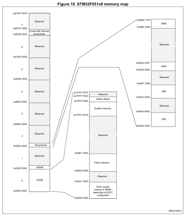
By default, the Flash memory on STM32F0 MCUs starts at 0x0800 0000, and the starting with 0x0000 0000 is used to map to the boot medium. This is Flash by default, but can be switched to map to external or internal RAM as well using the BOOT0/1 configuration bits:

This shows how flexible memory mapping is: without having to change the first-stage bootloader, the same address can always be loaded on boot, with the boot area’s contents easily switched to a different source.
It’s linking time
Before the compiled code can be assembled into the final firmware image, the linker tool has to know how to lay out the data as well as a few other details, such as the entry point. This information is described in a linker script, which uses a syntax the linker tool (usually ld) understands. Let’s run through the linker script for the STM32F042 target as an example:
ENTRY (Reset_Handler)
This specifies the symbol of the section (function) that will be put in the resulting binary file as the beginning of the .text (code) section. When the MCU boots, this is the first code that will be executed when booting from Flash memory. Here we target the Reset_Handler function.
_estack = 0x20001800;
This sets the address of the end of the stack (estack). The stack starts at 0x2000 0000 (SRAM start) and grows upwards to the indicated limit. With 6 kB SRAM (0x1800) on the STM32F042 MCU, this means that the stack is allowed to grow to the size of the entire SRAM. Obviously, this would leave no space for a dynamic allocation heap.
MEMORY
This section sets the different memory regions, along with their permissions, start and length. For the STM32F042 we only have two regions, FLASH (read/execute) and RAM (read/execute/write), of 32K and 6K byte length, respectively.
SECTIONS
This defines properties of the individual output sections. This also determines the order in which the sections end up in the Flash memory, which for our MCU means that the vector table and similar start-up code in .isr_vector goes first, followed by the firmware code in .text and constants in .rodata.
Next are the initialized data (.data) and uninitialized data (.bss) sections as well as a few more specialized sections. Finally, the ._user_heap_stack part, which is provided with some information that allows the linker to check that there is enough RAM and FLASH on the device for our code.
When we then add the link-time flag --print-memory-usage to ld, we can see something like this output when the objects are assembled into the final ELF image:
Memory region         Used Size  Region Size  %age Used
           FLASH:        9956 B        32 KB     30.38%
             RAM:        4008 B         6 KB     65.23%
Memory Mapping Unit Tests
So far we have gained a pretty good picture of the memory architecture of the STM32 MCUs and how our code fits on them. As anyone who has ever had to write register-level code on an MCU can probably attest, it can be rather frustrating to go through countless write-flash-broken-tweak-reflash-still-broken cycles, even when one can sling a debugger run or a dozen at the problem.
One approach which I have found rather useful here is to test my code first against a local test to see whether my code correctly writes the appropriate registers. This also allows for the integration into CI/CD systems, where a unit test can be run and afterwards the values of all registers compared automatically.
As an example, consider the GPIO peripheral test in my Nodate framework. It uses the GPIO class as one would normally in an STM32 firmware project, after which the registers of the GPIO peripheral are inspected. Since these tests do not run on an STM32 MCU, it’s obviously not using remote GDB magic on real hardware.
All Nodate classes include a common header (common.h) which normally includes the device-specific headers. Instead a different header in the same tests folder is included, which defines the peripheral structures and preprocessor statements which the Nodate code uses. For example the GPIO peripheral on STM32F0:
struct GPIO_TypeDef {
  __IO uint32_t MODER;        //!< GPIO port mode register,                     Address offset: 0x00
  __IO uint32_t OTYPER;       //!< GPIO port output type register,              Address offset: 0x04
  __IO uint32_t OSPEEDR;      //!< GPIO port output speed register,             Address offset: 0x08
  __IO uint32_t PUPDR;        //!< GPIO port pull-up/pull-down register,        Address offset: 0x0C
  __IO uint32_t IDR;          //!< GPIO port input data register,               Address offset: 0x10
  __IO uint32_t ODR;          //!< GPIO port output data register,              Address offset: 0x14
  __IO uint32_t BSRR;         //!< GPIO port bit set/reset register,      Address offset: 0x1A
  __IO uint32_t LCKR;         //!< GPIO port configuration lock register,       Address offset: 0x1C
  __IO uint32_t AFR[2];       //!< GPIO alternate function low register,  Address offset: 0x20-0x24
  __IO uint32_t BRR;          //!< GPIO bit reset register,                     Address offset: 0x28
};
In the associated common.cpp source file, instances of this type are created on the stack, with a pointer reference (e.g. GPIOA) being made available globally, as would happen otherwise by the preprocessor statements in the ST-provided device headers. Those would place these peripheral instances at specific offsets in RAM, of course, to match the peripheral registers. For our purposes that is not relevant, however, and simplifies our code significantly.
GPIO_TypeDef tGpioA;
GPIO_TypeDef* GPIOA = &tGpioA;
With this in place, the framework’s code will happily use these global variables as if they’re offsets into an MCU’s addressing space, enabling us to read out our GPIO registers and see how the code which we are testing did after each run.
Defining Success
Generally, each register is a 32-bit field. The simplest way to validate the test result is by using the MCU’s reference manual to determine beforehand what value we are expecting to read back there from the unsigned integer field. A simple integer comparison will then allow our validation system to spit out a ‘false’ or ‘correct’ response. While effective, this would also be fairly useless.
While a ‘pass’ is nice, one risks the Grand Canyon-sized trap for young players that is often summarized as ‘all tests green, exploded in production’. Which is to say that it’s impossible to say with certainty that a specific (unit) test is flawless, only that an issue has not been found yet. This is where manual verification is very useful, especially when test cases become larger and more convoluted.
In addition, it’s also essential to be able to get a printout of just what test result got rejected, with which input parameters. For most of the tests that I ran so far, I have used simple printouts of register values in the terminal, which I could then put alongside the registers in the reference manual for easy comparison. As shown in the above linked GPIO test file, this is done using the <bitset> STL header:
std::cout << "GPIOA" << std::endl;
	std::cout << "MODER:  \t" << std::bitset<32>(GPIOA->MODER) << std::endl;
	std::cout << "PUPDR:  \t" << std::bitset<32>(GPIOA->PUPDR) << std::endl;
	std::cout << "OTYPER: \t" << std::bitset<32>(GPIOA->OTYPER) << std::endl;
	std::cout << "OSPEEDR:\t" << std::bitset<32>(GPIOA->OSPEEDR) << std::endl;
	std::cout << "IDR:    \t" << std::bitset<32>(GPIOA->IDR) << std::endl;
	std::cout << "ODR:    \t" << std::bitset<32>(GPIOA->ODR) << std::endl;
This converts the uint32_t type to a bit field which is then printed like this:
GPIOA
MODER:          00000000000000000000000001000000
PUPDR:          00000000000000000000000001000100
OTYPER:         00000000000000000000000000000000
OSPEEDR:        00000000000000000000000000000000
IDR:            00000000000000000000000000000000
ODR:            00000000000000000000000000001000
One could make this somewhat more convenient to read by splitting it up into nibbles, but this will be left as an exercise for the reader here.
Wrapping up
There is a reason why this article focused mostly on the STM32F0 family of STM32 MCUs: their uncomplicated memory hierarchy. The F4, F7 and H7 families of MCUs have more complicated memory maps. The basics which were covered in this article still apply, however.
The flexibility of memory mapped I/O should be quite clear at this point, as well as how easy it is to integrate it into testing and validation systems. If you have any tips or pointers of your own on this or other topics covered in the article, feel free to leave them in the comments.


thank you for this
I also want to thank you for this educational article. Good read.
Where is libc especially crt0?
ARM Cortex doesn’t need crt0, just point the reset vector to a C function.
You need to put initial stack pointer in the vector table as well.
apropos of this, if i’m talking to the stm32 builtin bootloader, and want to have it start executing what’s already loaded into the flash, is the address of the reset handler the one i want to tell it to jump to? I was trying to tell it to go to 0x08000000 (and a few offsets around there) to no luck.
No, 0x08000000 contains first the initial value of the stack pointer, and then 0x08000004 contains the address of the reset vector. You’d need to add 1 to that address, and jump there.
turned out my problem was actually a bug in the bootloader:
https://community.st.com/s/question/0D70X000007QVZm/detail?s1oid=00Db0000000YtG6&s1nid=0DB0X000000DYbd&emkind=chatterCommentNotification&emvtk=Ty7owy80XYoqSl21hfn_fwSGko8mOjSJIJsrxBnneoc%3D&s1uid=0050X000009yaBl&emtm=1579772880090&fromEmail=1&s1ext=0
but thanks. :) by taking the time to help you motivated me to stick at this until i figured it out this time.
Phrase “left as an exercise for the reader” still gives me nightmares..
Wonderful article, thank you for it.
I’ve dropped this link before, but if you’re interested in linker scripts for STM32, then also have a peek at the “pandafruits STM32 primer”
http://pandafruits.com/stm32_primer/stm32_primer_hardware.php
Question: So it seems it should be possible to do direct port manipulation (e.g. simultaneous toggling of GPIO pins by writing to the GPIO output port register) on a STM32F103C8T6L, which is the part used on the popular “Blue-Pill” boards. I have a Blue-Pill working in the Arduino IDE, but when I try to use Arduino’s DDRB/D GPIO direction register command and the PORTB/D GPIO register value command to directly manipulate a port, I never see any pins toggle. So port-direct manipulation is not included for the STM32F103C8T6L in the Arduino IDE? If it isn’t supported that seems odd, everything else seems to work OK on the Blue-Pill in the Arduino IDE. Maybe there’s another way to do it, such as using some inline assembly code to directly manipulate the STM32F103C8T6L’s GPIO registers?
yes it’s possible by writing to the ODR register for the port in question , normally i do this with GPIOB = 1<< X; with x being the pin you wish to toggle. I use platformio with stm32cube but the same can be done in arduino.
For extra flexibility, use the BSRR register instead, so you can choose between SET/RESET/KEEP for each bit.
@Artenz, How do I manipulate the BSRR register in the Arduino IDE running the STM32 core? Thanks.
@darkspr1te: OK, I’ll try again with “GPIOB = 1 << X;". It's good to hear someone else has it working. Thanks.
As the meaning of register contents may vary, I like to format it as decimal, hexadecimal and binary, like:
43981 – 0xabcd – 0b10101011’11001101
Code I use to this end is in this GitHub Gist:
https://gist.github.com/martinmoene/58aacbc965ab79a521a6a9df782357c2
Tanks for the article. I read it and will have a look at how you use unit-tests. I will have a look at it, if i can adopt it to my projects.
However one thing bugged me, when I read this article this morning, so I had a look at the implementation.
The stack does not grow from the RAM-Start (0x20000000) to the end. The Stack starts at RAM-End (0x20001800) and grows downwards. You define _estack in the Linker script. This value is used in the startup code and put into the vector table (Assembler file startup_stm32f …s). The processor initializes his internal stack pointer register with this.
Global and or static variables which are available from the begin of the program are placed at the RAM-Start (0x20000000) and after that comes the heap. You can see this in the linker Script. “.data”, “.bss”, “.heap…” go into the RAM in this order. Starting at “RAM” which has the RAM-start address (0x20000000).
Other architectures may have a upwards growing stack pointer. On the Cortex-M you use the down growing one.
Yes, both M0 and M3 work as follow: ‘The processor uses a full descending stack. This means the stack pointer holds the address of the last stacked item in memory. When the processor pushes a new item onto the stack, it decrements the stack pointer and then writes the item to the new memory location. ‘
https://developer.arm.com/documentation/dui0552/a/the-cortex-m3-processor/programmers-model/stacks
I have never, and I do mean NEVER, encountered any rational processor architecture which does not have the stack grow downwards.
But then, of course, I only program in Assembly Language, and NOT in “bare metal”, whatever that particular new-age characterization is supposed to mean. Perhaps “bare metal” makes the stack grow upwards, in absolute opposition to the way all processors really work?
**********************************************
“People who are more than casually interested in computers should have at least some idea of what the underlying hardware is like. Otherwise the programs they write will be pretty weird.”–Donald Knuth
“By understanding a machine-oriented language [i.e., ASSEMBLY LANGUAGE], the programmer will tend to use a much more efficient method; it is much closer to reality.”— Donald Knuth
“When I use a word” [or phrase, in this case] Humpty Dumpty said in rather a scornful tone, “‘it means just what I choose it to mean — neither more nor less.”–Lewis Carroll
“The question is,” said Alice, “whether you can make words mean so many different things.”–Lewis Carroll