Every hacker has an assortment of USB to TTL-serial adapters kicking around in their lab, and we have all been annoyed that each one has a different pinout. You layout a PCB or breadboard for the Sparkfun flavor (GND, CTS, VCC, TXD, RXD, DTR), but when you begin troubleshooting all you can find is a CH340 board (GND, +5V, TXD, RXD, DTR, +3.3V). You have to jumper everything, and it becomes a mess. It wasn’t much better back in the days of RS-232 level signaling, either. While the pinouts were consistent, there were other headaches. Did the connection need a NULL modem adaptor? And if you were unlucky, you might need a DB-25 to DE-9 adaptor, and the really unlucky might need one or more gender changers. Surely there’s a better way.
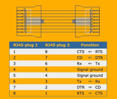
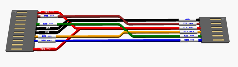
It turns out there was a better way, although it didn’t seem to have become as popular as one might expect. Back in 1987 [Dave Yost] formalized an interconnection scheme using RJ45 plugs and jacks while at Berkeley. The signals were arranged in a mirrored fashion so that each cable is always a crossover — just plug two cables back-to-back if you really need a straight thru connection.
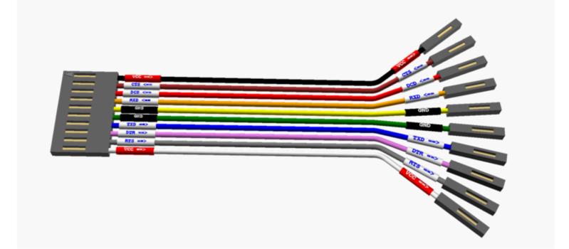
Even though he was dealing with RS-232 serial, nothing prevents us from using this scheme for logic level signaling. For example, consider the following 1×10 header pinout, where the original 8-pins are expanded to 10 to allow for power:
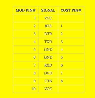
This is an extreme example, and can obviously be shrunk depending on how much handshaking, if any, or power is desired. Such a pinout lets you switch between DCE and DTE by simply flipping the connector around. And if a Dupont-style header slips off too easily in your applications, you could always use an RJ connector. This still doesn’t solve the Tower of Babel pinout problem with the USB-TTL adaptors. But standardizing on a serial pinout such as this for your projects and making cables or kludging your TTL adaptors will make serial debugging less painful.
Back when he released this scheme in 1987, [Dave] pontificated:
“Maybe one day before the year 2,000, the world will have a new, simple, high-speed, flow-controlled, standard type of connection for point-to-point applications currently using RS-232, with an adaptor available to talk to old, RS-232 equipment.”
Let us know your thoughts in the comments below.


unfortunate the clones were not a more syandard copy. i believe usb replaced rs232 but you see they change that every couple years, at least mini, micro and c…
Can’t help but feel that this is just too many pins, and the reversible nature of the connection necessitates VCC/GND duplication, sadly. There isn’t much that can be done about the VCC/GND duplication, sadly, save for installing FET-based rectifier bridges in each device. However, if there’s ever a cheap and accessible “single-package FET bridge” IC, it’d actually help a lot with the whole “need to duplicate power pins” thing, since you’d be able to use whichever polarity you’d like.
One can arrange the pinout symmetry ifor odd number pins connector. One center pin and 2 other pins are needed for power/ground. Going to even pin count would need 4 pins, so odd number of pins is optimal.
Or you could just split one end of the cable into a straght and a reversed connector and do away with all the screwy waste of space for a reversible connector.
Yeah, point noted. The intent wasn’t to provide a ready-to-roll solution, but to present the scheme embodied in Mr. Yost’s system and to get people thinking if it could be adapted to their designs.
Assuming you want to minimize the number of pins, a reasonable goal, I would suggest the following: Since you often don’t need power nor handshaking, make the “core” pinout always “RX.GND.GND.TX”. Next, I guess it depends on whether providing power or handshaking is more important. If power, then “VCC.RX.GND.GND.TX.VCC”, and for those designs that require handshaking, add them after the VCC pins. Instead of FETs, I wonder if a simple diode bridge might work? Something like “RX.PWR.PWR.TX”. And if you’re okay with an odd number of pins, the middle ground doesn’t have to be doubled… “VCC.RX.GND.RX.VCC” would work, too.
Also, if you were to standardize on the RJ connectors of the original plan, but with logic level signaling, you might as well use all 8 pins. The size difference isn’t that great between say a 4-position and an 8-position plug, as opposed to their 1xN pin header counterparts.
A simple diode bridge won’t work because of the voltage drop (dropping 3.3V further than 3.0V will prove devastating for an ESP8266), but a FET bridge, as I proposed, might.
An odd number of connectors might very well work, indeed. I didn’t talk about it because it’d interfere with RJ45 but, now that I think of it, I wouldn’t standartize on RJ45 either – too prevalent as network connectors already, quite a bit of potential for confusion. Perhaps, JST of some kind – SH or some 1.25mm option? And pin headers would work well as an alternative.
So use an odd number of pins and single ground for header connectors, even number and two grounds for RJ. Problem solved.
If you are going to double up the pin count, might as well make a cable with 2 ends – one with straight connection and one “reversed”. You won’t misalign the connection or waste space for the header on the PCB.
The pin count isn’t really doubled, now, is it? Only GND and VCC pins are doubled, if you think of it, a “power, ground and UART” connection would take 6 pins in such a configuration (if we place them next to the UART pins as opposed to outside) instead of usual 4 pin-headers of unknown pinout.
“Maybe one day before the year 2,000, the world will have a new, simple, high-speed, flow-controlled, standard type of connection for point-to-point applications currently using RS-232, with an adaptor available to talk to old, RS-232 equipment.”
That’s basically USB, for a certain definition of “simple”.
1) he wants flow-controlled, USB is NOT flow-controlled, the data and the timing for the data are both sent down the same wires, both the + and the – wires are bi-directional and there is no wires to force the sender to pause sending and vicea-versa
2) USB is not a standard, unless your talking about power/charging, but for data; YOU NEED A VERY EXPENSIVE LICENSE. (more then most people make in a month)
3) although you can find USB->rs232 adaptors, (this article is about them) they DO NOT work with all rs232c devices. due to USB network packet-size having a minimum and any agregating of said packages causes a need to send extra dumy data to force a packet-transmission (full-buffer) and any latency loss due to this huge increase of data. therefore you never know juuust WHEN that wire will switch-on, important for if the original application was relying on access to a hardware port, able to be accurately and EXACTLY commanded just like when writing assembler on a microcontroller
4) even USB adaptors with flow-control usually lack one or two of the de9-version’s signals as well as all the db25’s extra signals (a FULL db25 rs232 had TWO serial ports but not since the last few decades, not to mention loopback/ect are all missing) … say im wondering if the whole IRQ/DMA conflict was rooted in having a second port within a port? maybe originally there was 4 IRQ’s for 4 ports but now 2 IRQ’s for 4 ports… would explain some funky cables ive seen.
re: 1
all true as far as it goes. but it’s all host controlled, and a USB host generally knows more about the device it is talking to than old-school devices did. there’s all sorts of fancy descriptor systems and such, and you can layer on more if need be. and speaking of layering on more, there’s no reason you can’t have a second endpoint on a device which provides flow control information to the host, which it honors. (flow control in the other direction can be managed by the host simply not requesting data when it doesn’t want it.)
re: 2
any licensing for USB is included in the parts that you’re using which include it. while you can make your own UART, and it’s not unreasonable inside of programmable logic, you’re generally using some already provided UART. so what’s the difference with using some already provided USB interface that you’ve already paid your micro-cent license for?
re: 4
huh? the ISA bus had physical pins for each interrupt. there were only so many of them. the processor couldn’t determine which card pulled the line, only that it had been pulled.
USB is absolutely flow controlled!
Device to host: The host will only issue IN tokens to the peripheral device when it is able to receive data (ie has buffer space – in effect, an outstanding read request). If the host can’t accept data, it won’t issue tokens and the peripheral has to buffer it.
Host to device: The device can NAK OUT tokens from the host when it does not have room for data, stalling the outbound pipe. The USB controllers themselves will do this if their FIFOs are full.
USB is a standard, and you can download the specs easily. The only thing that costs money is getting a VID (vendor ID). Everyone with a vendor ID then has a 16 bit device ID field they can use. Some people have taken advantage of the less tight license terms back in the day and are giving out PIDs to open source projects too. eg, see https://pid.codes/ (and hackaday story on this back in the day).
In reality, if you’re just doing something on your own bench you have a 2^32 space to pick a random VID/PID for your thing, and as most of that space is empty you’ll be just fine picking a random number….
Yay for a more universal pinout, nay for a freaking 10 pin connector for a god damn UART port.
Here is what I would change on your pinout :
– make it an odd number of pins by not doubling up the ground pin, shaving a pin while keeping symmetry
– put vcc on the “second” row after tx/rx. for most people, power is waaaaay more useful than cts/rts/xxx stuff
– swap the order of RTS/DTR (and their siblings). while I virtually never use them, RTS/CTS are kind of more useful and more widely available than DTR/DCD
Basically, the further you stray away from the center ground pin, the less important the signal is, allowing for some “light” variants for simple devices. Because honestly, how often do you use the flow control signals compared to providing power to some random microcontroller board through you usb/uart adapter?
this would make the following pinouts:
– full: RTS | DTR | VCC | TXD | GND | RXD | VCC | DCD | CTS
– regular: VCC | TXD | GND | RXD | VCC
– light: TXD | GND | RXD
You’d typically place the regular one on some board that is low power enough that it might be powered from a usb/uart adapter (arduinos and the like), or the light variant on anything self-powered (your run of the mill ARM SBC with its own power supply).
However, nice idea! [please insert releavant xkcd here]
I like this plan. I’m 50/50 on the double ground pin. I’ve had minor trouble getting some odd-pin sockets, and I can still see some advantages to using RJ connector in some designs (although an RJ connector doesn’t HAVE to use all 8 pins). I rarely run into handshaking signals, too, these days. Sometimes needed for really high speed links, or to shoehorn a RS485 interface. More commonly I’ve used them to reset and enter boot mode on microcontrollers or wish I didn’t have them when DTR asserts on connect and resets GRBL.
I think you may be looking for ‘yea’ and not ‘yay’. ‘Yay or nay’ is a common misstatement of ‘yea or nay’.
that’s a lot of board space to dedicate to a uart that’s probably there for some optional purpose.
probably cheaper just to keep your cables/adapters organized.
do the flow control signals see much use these days? i just put TX/RX/GND pins on the board, actually silkscreen every pin, and then go nuts with one of those rpi ftdi cables.
I think the advantage here is you only put the number of pins needed by your board. The adaptor can support full UART when necessary.
Rather than invoke the relevant XKCD, seems to me it’d be better to just solder wires to the UART board with labeled female dupont terminated ends. That should take most of the frustration out.
+1
if they are seperate plugs for each, then you dont need any pinout, only labels
besides, i always thought ground should be on the end-most pins so static is always dis-charged before any sensitive signals connect AND the second ground to connect is already at equal voltage and does not spark and any existing wear is rubbed off as power is passed through other ground. more of a hot-swap thing i guess?
As suggested by 8bitwiz below, I think hot swap connectors are usually designed so the ground and/or power pins are longer. Take USB for example. Various connector shapes and pin outs, but on all of them that I have seen the GND and 5V pins are longer so they connect first.
I don’t think putting ground on the ends is a reliable means of ensuring it mates first. You could easily have slight differences in contact length that still cause other pins to mate first.
Plus, hot swapping is less about ESD and more about ensuring data lines don’t exceed Vcc. That will easily kill a MCU. Just read any of the spec sheets absolute maximum ratings on voltage from data lines to Vcc. It’s probably <1 V. So if you hit it with 5 V from a TTL or 3.3 V from a CMOS level signal, and Vcc is still sitting at same level as GND, you can cause lots of damage.
I don’t like the idea of soldering wires to a board because they will inevitably break from bending stress. You can’t easily replace them, nor can you remove them when no longer needed. Header pins on both ends are much better. And if you’re worried about ground first, use a longer header pin, they’re not hard to swap out of the plastic bar before soldering.
And I think the real problem with hot plugging is having odd voltage potentials between pins without a ground reference, or with having a power pin in the connector. I worked on a product which ran I2C in the same connector with 24VDC power, hot plugging would often blow out the I2C pins on multiple devices! The design was not my fault, but I certainly did learn from it.
My brother once circulated a company guide to RS-232 which included the advice “The pinout is not completely standardized except you can expect that mains will not be present. But even that is not guaranteed”.
Lightning and USB-C cabling are better than I imagined while I (apparently) was pontiff. I went to Berkeley, but only to visit.
Just like to say thanks for showing up here. I agree we have come a very long way, but I am also happy to see useful stuff like this discussed here. Some of the older tricks are still really helpful for people tinkering at home.
Thanks for your hospitality.
Just FYI: The Yost pinout is the same pinout as what Cisco uses for their RJ45 serial console connectors, and the (non RJ45 to DB9) cables are a simple ‘rolled’ 1-8 to 8-1.
I started using EIA-561 way back when
https://commons.wikimedia.org/wiki/File:DE-9_to_8P8C_console_cable_pinouts.svg