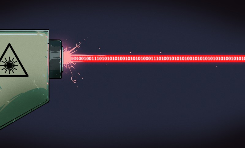
We live in the information age where access to the internet is considered a fundamental human right. Exercising this right does largely rely on the technological advances made in optical communication. Using light to send information has a long history: from ancient Greece, through Claude Chappe’s semaphore towers and Alexander Graham Bell’s photophone, to fiber optic networks and future satellite internet constellations currently developed by tech giants.
Let’s dive a little bit deeper into the technologies that were used to spread information with the help of light throughout history.
Semaphores and Heliographs
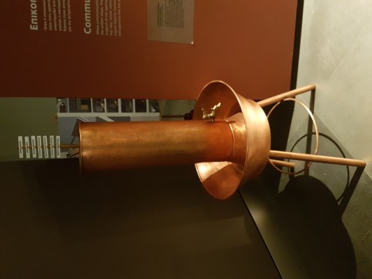
Since light can travel in air much further than sound, visual communication has always been the method of choice to broadcast information over long distances. One of the earliest examples is the Phryctoriae from ancient Greece, a system of towers built on mountaintops that could send messages by lighting torches. Allegedly, this is how the news of the fall of Troy was spread throughout the country. The Greeks came up with different methods of encoding messages. One was to have two groups of five torches where each torch would represent the row and column in a 5×5 matrix of Greek letters known as the Polybius square. The other is the hydraulic telegraph which consisted of a container filled with water and a vertical rod floating within. The rod was inscribed with various messages along its height. When the remote torch signal was received, water from the container was slowly drained until the torch went out again. Through the position of the inscribed rod, the water level could be correlated with a specific message.
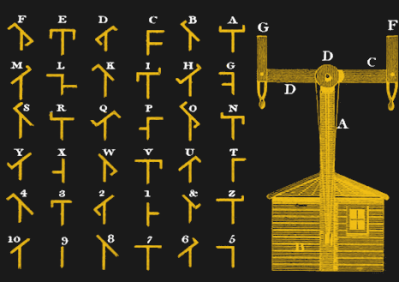
In the late 18th century the Chappe brothers devised and erected a network of semaphore towers in France for military communication. On the top of each tower was a semaphore comprised of two movable wooden arms connected by a crossbar. By adjusting the angle of each arm and the crossbar a total of 196 symbols could be displayed which were observed from the next tower with a telescope. By waiting for the downline station to copy the symbol, the communications protocol already included an ACK signal as a means of flow control. In terms of data rate, the system could reach about 2-3 symbols per minute; taking about two minutes for a symbol to travel from Paris to Lille over 22 stations and 230 km.
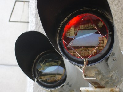
In the late 19th and early 20th century, the heliograph was widely used for military communication. It consisted of a mirror that could be pivoted or blocked with a shutter to generate flashes of sunlight and was mostly used to transmit Morse code. Even though the heliograph was rendered obsolete by most armies in the 1940s it was still used by Afghan forces during the Soviet invasion in the 1980s and is still included in many survival kits for emergency signaling.
Bell’s Greatest Invention
Many of you probably know the kind of DIY projects where an audio signal is transmitted by a laser beam which is surprisingly easy to build. The invention goes back to Alexander Graham Bell, who in 1880 invented the photophone which he thought to be his “greatest invention ever made, greater than the telephone”. It could transmit speech wirelessly using a flexible mirror mounted at the end of a speaking tube to modulate the intensity of the reflected sunlight. The receiver part consisted of a selenium photocell at the focus of a parabolic mirror. Bell and his assistant Tainter also build nonelectric receivers using materials coated with lampblack thereby discovering the photoacoustic effect. Even though Bell was immensely proud of his invention up to the point where he wanted to name his second daughter “photophone”, the device never really hit it off. This was mainly because radio wave transmissions as pioneered by Marconi a few years later far surpassed the distance achievable with light and did not require a direct line of sight.
Guiding Light Through Glass
Apart from a few military projects, telecommunication in the 20th century was mainly conducted via coaxial cables and microwave signals in the relatively low frequency 1-10 GHz range. This was until the development of fiber-optic communications in the 1970s, which was enabled by the invention of low-loss optical fibers and semiconductor lasers.
The main drawback of high-speed communication via coaxial cables is that signals have to be repeated about every kilometer to make up for cable losses. With wireless radio frequency (RF) communication, the repeater spacing can be a lot larger, but in both cases, the bandwidth is limited to ~100 Mbit/s due to the “low” frequency of the RF carrier.
The frequency of visible and infrared light is about 1014 Hz, much higher than the 109 Hz “Gigahertz” frequencies used for RF communication. As a consequence, the optical spectrum is about 2600 times wider, in terms of frequency, than the entire RF spectrum. This broader bandwidth enables much higher data rates.
One of the first applications of fiber optics included the control of short-range missiles through a fiber optic tether attached to the back of the missile that rapidly unspooled during flight. In 1977, General Telephone and Electronics sent the world’s first live telephone traffic through a fiber-optic system at 6 Mbit/s. Today, the worldwide optical fiber network is estimated to span more than 400 million kilometers, close to three times the distance to the sun.
Optical fiber communication soon far surpassed the transmission speeds of RF communication and was further boosted by multiplexing techniques like wavelength-division multiplexing (sending multiple wavelengths down the same fiber), time-division multiplexing (separating signals by their arrival times), or space-division multiplexing (using multi-core or multimode fibers). Using a combination of these techniques, data rates of up to 11 Pbit/s have been demonstrated in the lab. The low light losses of 0.2 dB/km (i.e. the intensity loses only around 5% after 1 km) in modern fiber cables enable repeater spacings of ~80 km.
Internet From Your Light Bulb
We still mostly use the RF spectrum for wireless communication, but there has been some renewed interest in wireless optical. At short distances, this goes under the catchy name LiFi and became a trendy topic about 10 years ago, partly triggered by this TED talk. It advertised the idea of using the already existing infrastructure of regular LED lighting for data transmission.
Some of the advantages being that it is more efficient, more secure against eavesdropping, and enables higher bandwidths. However, the idea of having your WiFi at home transmitted through your light bulbs never really became popular. Arguably one of the reasons might be that having a connection that depends on light shining onto your device is not always considered an advantage. Up to now, LiFi is only used in some industrial applications where electromagnetic interference or security are important issues. But lower bandwidth versions are prime areas for hacking.
Going Long Range
The optical transmission of data over long ranges goes under the name free-space optical communication (FSO). You may remember Facebook’s Aquila drone program, a giant solar-powered vehicle that should stay in the stratosphere for months to beam internet to remote areas. In addition to standard GHz frequency bands for air-to-ground communication, they were also experimenting with free-space optical links. The technology behind this is still similar to Bell`s photophone, although we now use IR lasers instead of sunlight. Shortly after Facebook canceled its Aquila drone program in 2018, it became public that they are working on a similar system that uses satellites instead of drones due to technical difficulties. In September 2020, Facebook’s subsidiary PointView Tech launched the Athena satellite which is supposed to test a laser ground link.
Google (or Alphabet if you prefer) is/was working on similar projects called Loon and Taara. Maya Posh just wrote a more detailed article about Loon. Its goal was to send a network of high-altitude balloons into the stratosphere providing internet access to underserved areas, but the project was shut down a few weeks ago. Within project Loon a 155 Mbit/s laser communication between two balloons more than 100 km apart was achieved. Project Taraa builds on this success and aims at developing towers that use free-space laser communication to deliver 20 Gbit/s connectivity over distances of 20 km. Compared to installing fiber optic cables, this would be a cost-effective and quickly deployable way to bring high-speed connectivity to remote areas.
Similar systems are already commercially available by a company called Koruza delivering up to 10 Gbit/s, albeit over a modest range of 150 m. Of course, hackers have also played around with the technology. Way back in 2001, the open-source project Ronja provides instructions to build a low-cost transmitter-receiver pair capable of 10 Mbit/s communication over a 1.4 km range. As a transmitter it just uses a standard red LED collimated by large lenses salvaged from magnifying glasses. Ronja works in most weather conditions including rain and snow but fails during fog.
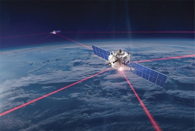
This marks one of the major downsides of FSO. While requiring a direct line of sight makes communication more secure, it also imposes some restrictions. Cloudy weather can make satellite-to-ground communications break up, so microwave signals are considered more viable in this case. However, future internet satellite constellations like SpaceX’s Starlink, OneWeb, or Amazon’s Project Kuiper are likely to use laser communication as a secure, high bandwidth link in between satellites. At the forefront of developing this hardware are the German companies Tesat and Mynaric. Both companies offer laser systems with data rates of up to 10 Gbit/s between LEO satellites and ground stations. For inter-satellite linking Tesat’s laser systems can achieve 1.8 Gbit/s between geosynchronous satellites up to 80,000 km apart while Mynaric’s laser communication products carry 10 Gbit/s over distances up to 8,000 km.
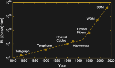
The advancement of optical communication from the ancient Phryctoriae to modern laser communication was driven by the goal to expand humanity’s interconnectedness. Since the beginning, the communication data rate has increased by ~12 orders of magnitude and culminated in a space race to provide global broadband access via satellite networks. Bringing internet access to underserved areas is certainly a noble goal but we may also question the meaningfulness of enabling ever-higher bandwidths when it is mostly devoured by video streaming. Although there is no strict fundamental limit to the bitrate achievable with optical communication it also interesting to ask the question of what comes beyond, perhaps neutrino communication?


Don’t forget the work by one of our Hero’s; Forrect Mims. Great things done by Forest with optical and laser communications.
Optical communication always will remember him.
Oh Ronja, I was infatuated with that when I got started in electronics
I never heard of this, Ronja. It’s pretty cool. From the late 90s to early 2000s I worked as an long haul wireless tech which included FSO tech. Lightpointe had a series of devices that were duplex and some of which had a motorized system for connection. If power was cut to one side the other side would seek a signal and end up following stars in the night sky, so UPSes were important to keep wackiness from happening regularly. Always a laugh to have to go out in the desert on a rainy, dusty, windy day to find the thing tracking who knows what. Never had these problems with microwaves.
https://www.lightpointe.com/the-history
Every time I see that picture of the Chappe semaphore, the only thing I can think of is “Why doesn’t the code for T look like a ‘T’?”
( I sepend way too much time doing projects with serial communication and tend to fixate on things like this, I guess )
Because it was supposed to be secret communications, only the end stations had the right books to decypher the data.
You can find more information on Wikipedia:
(FR): https://fr.wikipedia.org/wiki/S%C3%A9maphore_(communication)
(EN): https://en.wikipedia.org/wiki/Optical_telegraph
One interesting fact is that some people actually managed to “hack” it and make profits out of it (In french, but right click, translate to english!): https://blog.francetvinfo.fr/deja-vu/2017/10/10/le-piratage-du-systeme-chappe-ancetre-des-cyber-attaques-modernes.html
Clacks anyone?
GNUTerryPrachett
I was thinking the same thing if you combine a Polybius square with a semaphore tower you have a clacks tower. Someone get the bursar some dried frog pills pills he’s at it again.
Or give him enough so he hallucinates that he is sane.
Not to long back I was wondering about using a fiber optic plug as a focal point to a beam collimator going into a looks like now under $100 SFP+ adapter card. https://en.wikipedia.org/wiki/Small_form-factor_pluggable_transceiver
Last left wondering what pulse train methodology would be most efficient at transmitting for longest distance, since a CW beam would interact more with the environment masses in the trajectory and I’m not certain the range of pulse train methods and their wireless performance in the range of environmental conditions. Might need a translator/adapter of some sort to optimize the wireless to wired method was thinking too.
Found this Hackaday link too: https://hackaday.com/2013/05/14/retrotechtacular-first-laser-transmitter-built-50-years-ago/
I remember a project where a guy used some off the shelf fiber optic trancievers with optics and was able to get 1gig a few hundred feet. His project was mostly on trying to keep the optics in focus with the small sway of the houses and change in temp. Sorry no link.
Makes sense. Has me thinking overboard now like mounting, thinking only one side needed even if two way comm, on a multi-axis gimbal with target tracking of the light pipe/target. Characterizing the range of environmental conditions to calibrate accordingly would be interesting since thinking can have a pre-comm protocol condition check. I guess I’d have to research some more the handshake or error checking protocols for the SFP+ and other LiFi or FSO designs since seems I’m thinking there must be some sort of way to concentrate down the simplest method to error check for the environmental conditions… wondering even as or switching to optimal least absorbing frequencies to better aid like in the UV-Vis range.
No reason to overthink lifi. Treat it like any other medium look at Shared media access is being worked on all the time copy a fdma or tdma design even use a controller and just work on the physical side ending with a interface back to a computer nic or switch port interfacing with their GMII. It’s what some the early free space optics did when an Aui was easy to access and interface with simple circuits.
Does the photo of the Hydraulic Telegraph need to be rotated 90 degrees clockwise?
Interesting. Not on my browser.
Does it look like a vertical chimney to you? It should.
It didn’t in my browser at my former workplace.
But it looks okay here at home.
I recall hearing the fog closed in as the semaphores signaled “Wellington defeated”
causing much panic until the fog lifted and the entire message “Wellington defeated Napoleon at Waterloo” was transmitted.
(Urban Legend?)
Back around 1975, when I was 13 years old, I built a light-based system that used a flashlight bulb and an amplifier on the transmitting end, and a cadmium sulfide photo sensor and an amplifier on the receive side. It used some lenses from a science kit from Edmund’s Scientific. It transmitted voice fairly well.
What lightbulb wouldnt have persistence of illumination at audible frequenvies?
Being 46 years ago and me being about 13 at the time, I can’t say what bulb was used. It did respond fast enough for recognizable voice transmissions, I suspect that the high-frequency response was very poor. I remember that it was driven by a TO-3 power transistor and biased by a potentiometer, I suspect bad non-linearity as well. I was quite happy that it worked at all.
This was a fairly standard experiment for kids interested in electronics at the time. Not belittling you, mythoughts62, just suggesting that Erik Johnson has some research ahead of him.
Yes. What else was there except incandescent bulbs before LEDs?
I can picture a project in Popular Electronics in the sixties, though maybe it used an oscillator to feed the bulb and modulated the oscilkator. Almost seems like a John Simonton project, before there was PAIA.
People with access to lasers would transmit audio, but I’m not sure when those became viable at home. I suspect the Amateur Scientist in Scientific American had a project, but not likely built bynmany. In 1970 Popular and Electronics had a laser project, by then laser tubes were “within range” price wise. But right about then solid state lasers were starting to be a thing in hobby circles.
“What else was there except incandescent bulbs before LEDs”
Neons – capable of much better frequency response than incandescent.
You don’t have to drive the bulb fully on or fully off.
The signal is Amplitude Modulation (AM) so it can be amplified.
You can use very very little fluctuation of light intensity and then amplify the received signal as long as you keep above the noise floor of the sensor.
I was trying to find the Monty Python skit “Wuthering Heights in semaphore”,
but, I dunno, maybe YT doesn’t have it.
Looks like has been blocked, though an excerpt is here: https://twitter.com/fionnfoley/status/1318228487392710656
Scrolling down in the tweets you’ll find another skit: https://twitter.com/i/status/1318237229190402049
Another Monly Python skit:
https://youtu.be/sZEeBqZsmQM
Nice write up but in one aspect my memory serves me differently.
Fiber optics overtook RF in bandwidth and speed lone before advanced modulation techniques.
Then later modulation techniques took advantage of a prior development that caused the increase in speed, not the other way around.
Early lasers were not very power efficient. Consequently they were slow to turn on and fast to turn off. The slow turn on was the constraint limiting bandwidth.
As they became more power efficient and faster to turn on bandwidth improved quite a lot. They overtook RF bandwidth at this stage.
Then later semiconductor lasers were so fast to turn on and off that the constraining factor was the speed of the bi-polar transistors driving the laser on and off.
As other technologies replaced the bi-polar transistors there was a second great increase of speed and due to this increase, other more efficient modulation techniques could be used.
The early modulation was NRZ (Non-Return to Zero) or HDBP (Hi Density Bi-Polar) or similar. These modulation techniques kept the laser on and modulated intensity in a digital format so as to avoid saturation the bi-polar drive transistors.
The Bell photophone idea did get adopted by the German military during the World War 2 era – the Lichtsprechgerat 80 (LiSpr 80). Helge Fyske LA6NCA has some good info about them on his webpage. Kind of goofy looking things.
If done well, I bet there could be some really good applications for free space optical communication to provide uncensorable cross-order links in and out of dictatorships. The jackboots wouldn’t know about that low power laser beam between two mountains, one in a free country, unless they happened to have a sensor pass right through it. A low power beam shouldn’t be particularly visible in air off-axis except in fog, when you’d have to shut down anyway as you’d get no useful throughput.
“A low power beam shouldn’t be particularly visible in air”
Especially if you use infra-red.
I’m interested in some DIY Li-FI FSO work for short ranges (10s of metres), with relativly wide angle illumination (say 20 degree cones). Anyone know of part numbers and datahseets for:
A) LEDs, optical or IR, which can modulate at tens or hundreds of MHz and still give a good square wave
and
B) equivalents of TSOP38238 like modulation sensitive receivers, optical too even thoguh the TSOP range are just IR, able to work with tens or hundreds of MHz carrier frequencies? Or phototransistors, again optical or IR, which can pick up such 10s or 100s of MHz “square” waves and then be fed in to op amp systems to do the filtering to leave only carrier modulated stuff and not background junk. I’ve never found a phototransistor which doesn’t totally blur out above 10KHz.
Thanks
B> looked at using reversed bias pin photodiodes / avalanche photodiodes.
I wonder if a TOSlink output from a computer could be repurposed via driver software to send data other than audio? Would also need a TOSlink input for the computer to get data back.
S/PDIF, which is what is usually sent over TOSLINK, has a “passthrough” mode. This is meant for things like AC-3 encoded surround sound. So yes, it’s not only possible, but actually regularly done. All you’d need to do is to package your data as “non-audio”. Bitrate is rather low though.
I haven’t found the passthrough mode you mentioned, perhaps my search-fu is weak :-) According to Wikipedia, the current maximum bitrate (for audio) is 125 Mbps, so the bitrate should be better than “rather low”. Can you provide some links? Have you seen the TOSlink CNC project? http://goodenoughcnc.eu/other-projects/
“The invention goes back to Alexander Graham Bell, who in 1880 invented the photophone which he thought to be his “greatest invention ever made, greater than the telephone”” .
Propaganda at it’s best, IMHO. 😉
There was more than one inventor of the telephone.:
The German inventor Philipp Reis in 1861, ~15 years before Bell..
The Italian inventor Antonio Santi Giuseppe Meucci in ca. 1854-1860..
And probably many more.
Next time, someone maybe boldy claims that ENIAC was the first universal, programmable digital computer.. 🙄
Modulated Light DX
http://www.modulatedlight.org/Modulated_Light_DX/MODULATED_LIGHT_DX.html
167km in 2005
Wow, good link. Thank You.
Yeah great link! Appreciate that. Confirmed what I was thinking… using higher frequency source… like blue DVD first off or some other better laser/source with telescope lens optics.
Never thought about using Fresnel lenses… has me off on projection screen TV scale lenses and now am thinking would be humorous and maybe even better using parabolic dishes or even better troughs.
Still wondering what the best pulse train methodology is and if modern modulation/multiplexing can improve on the performance in the same environmental conditions, albeit with DSP latency. Thinking the basic Morse code and analog signals processing for starters.
OpenVLC Project is working along these lines.
https://ieeexplore.ieee.org/document/8767252
I know everyone stands on the shoulders of the previous, but Professor Alf Adams and the discovery of the strained-layer quantum-well laser which allowed for optical laser communication. The work he did is completely under rated. https://en.wikipedia.org/wiki/Strained_quantum-well_laser
Wow I just had an amazing read! Thank you for sharing!
One of the first techy people I ever knew was a guy I worked for one summer who designed some sort of relays for light communications. I can only assume it was military related as he would not directly discuss it in any form but I saw a few framed patents on his wall for similar vein builds iirc. His wife was a trove of secondhand knowledge though lol. She actually listened to some of his random fussing and could dictate almost word for word. I could not really ever glean what was going on at the time but man I loved the times I had to work in his basement. Loads of electronic diagnostic gear of various generations. I could not touch it but it was one of those moments in life we rarely get where you can just stare in awe while your mind spins imaginative uses for things and you drool with your mouth open lol.
I remember back in the 70’s an article in an old magazine called Radio TV Experimenter on how to build an infrared audio transceiver using parts from flashlights.