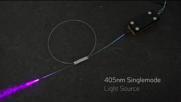
A rectangular black box is shown, connected to a coil of fiber-optic wire. Out of the end of the fiber, purple light is emitted. A label in the lower right corner says "405nm Singlemode Light Source".

Building A Fiber-Coupled Laser Source For Precision Optics

Laser diodes are convenient light sources, but for precise optical work their often-elliptical beam profile leaves something to be desired. One way to get around this is to couple the beam into a single-mode optical fiber, which then emits a circular Gaussian beam from the other end. For more advanced experiments, therefore, [Diffraction Limited] built this fiber-coupled laser source.

The simplest approach is to place the fiber directly against a light source, but this results in most of the light missing the three-micron fiber core. Optical fibers have an acceptance cone, and only light approaching from within this cone is coupled into the fiber. The design therefore uses an aspheric lens to focus light from the laser diode down to a tiny point matching the diameter of the fiber core, creating a cone of incoming light narrower than the acceptance cone.

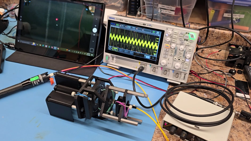
The body of the laser source was CNC machined out of brass, with the laser-diode press-fit in one end. The lens stands in front of the diode, and was glued in place so that its focal point was just above the end of a mounting pin for the glass fiber. Positioning and fixing the fiber in place was the biggest challenge; [Diffraction Limited] could use the micro-manipulator from a previous video to position the fiber, but the UV-set glue used to fix it in place shrinks during curing, pulling it out of position. To deal with this, two set screws under the mounting pin allowed its position to be adjusted slightly after gluing. As expected, adhesive shrinkage meant that the completed source initially produced no light, but after the set screws were adjusted, the beam appeared.

For more on fiber-coupled lasers, check out [Les Wright]’s work. If you don’t have access to an aspheric lens, an anti-bumping bead could be a reasonable alternative.

The Walls Don’t Have Ears, But Fiber Optic Does

You normally think of fiber optic as something used in network cables. However, scientists employ dedicated fibers to detect earthquakes. In simple terms, they fire a laser down the fiber and watch reflections caused by imperfections. When vibrations hit the cable, it changes the defects, which show up in the return pattern. However, with the right techniques, those vibrations could just as easily be from people speaking near the cable.

If you are alarmed, there’s good news and bad news. The good news is that the technique seems to be limited to coils of fiber that are not buried, and you have to be within about 5 meters of the fiber. The bad news is that there is plenty of dark cable all over the place. Besides, if researchers can do this successfully, you would imagine three-letter agencies around the world could do it even better.

Continue reading “The Walls Don’t Have Ears, But Fiber Optic Does”

A Digital Audio Recorder For TOSLink

Every now and then in our travels we come upon a project with such an obvious need that it’s almost a surprise nobody has thought of doing it before. So it is with [Elehobica]’s project, an audio recorder for S/PDIF audio streams. It’s the device you could have used, years ago!

S/PDIF, or its optical fiber cousin TOSLINK, is the digital output you’ll find on the back of Hi-Fi equipment, it’s a serial encoding of an uncompressed digital audio data stream dating from the era when CDs were new. Its relative simplicity may be what’s given it longevity — it’s easy to implement so it plugs into pretty much everything.

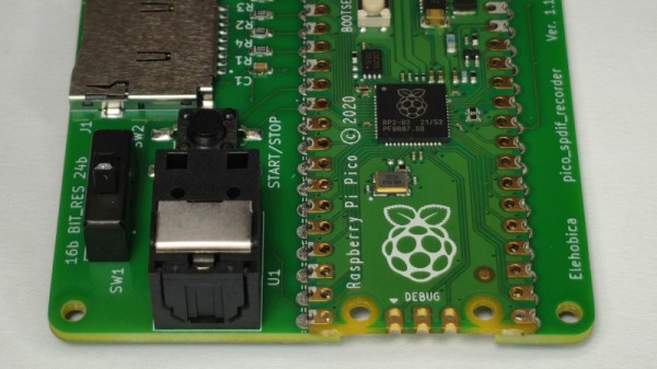
Perhaps back in the day it might have been a pain for an 8-bit microprocessor to handle, but in 2026 it’s no bother for a Raspberry Pi Pico. The project is a small PCB with the Pico, a few interface components, and an SD card socket, and it sends what it hears on the input to the card as WAV files. We particularly like its smart sample rate and bit depth detection, and the way it cuts up tracks based on periods of silence. If you work with SPD/IF, this is going to be a useful tool.

Perhaps it could even be fed with a laser!

Fiber Optic Lamp Modified To Be Scarily Bright

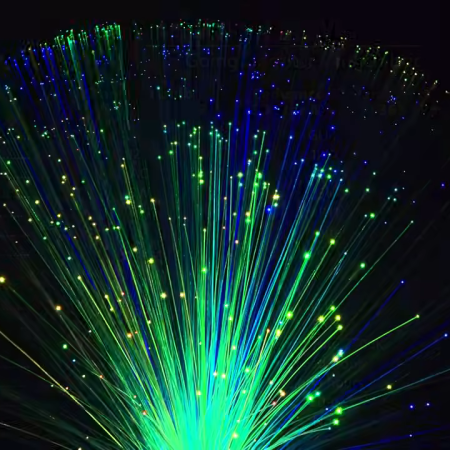
[Brainiac75] is a fan of fiber optic lamps, except for one thing—they’re often remarkably dim. Thus, they set out to hack the technology to deliver terrifying amounts of light while still retaining their quirky charm.

Older fiber optic lamps use a dim filament lamp or halogen lamp to light them up. They also often feature a spinning color disk to vary the light patterns, which does have the side effect of absorbing some of the already-limited light output.

When it came to upgrading his own decades-old lamp, [Braniac75] decided to initially stick within the specs of the original halogen lamp. The fixture was rated for 12 volts at 5 watts, with a GU4/GZ4 compatible base, and white light was desired so the color wheel could still do its thing.  Swapping out the original 5 W halogen for a 2.5 W LED unit brought a big upgrade in brightness, since the latter is roughly equivalent to a 20 W halogen in light output. Upgrading to a 4.2 W LED pushed things even further, greatly improving the look of the lamp.

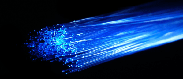
The video also explores modding a modern fiber optic lamp, too. It was incredibly cheap, running off batteries and using a single color-changing LED to illuminate the fibers. [Braniac75] decided to try illuminating the plastic fibers with an RGB stage lighting laser rig—namely, the LaserCube Ultra 7.5 W from Wicked Lasers. With this kind of juice, the fiber lamp is eye-searingly bright, quite literally, and difficult to film. However, with the laser output dialed way down, the lamp looks amazing—with rich saturated colors dancing across the fiber bundle as the lasers do their thing.

If you’ve ever wanted to build a fiber lamp that doesn’t look like a cheap gimmick, now you know how. We’ve looked at weird applications for these lamps before, too.

Continue reading “Fiber Optic Lamp Modified To Be Scarily Bright”

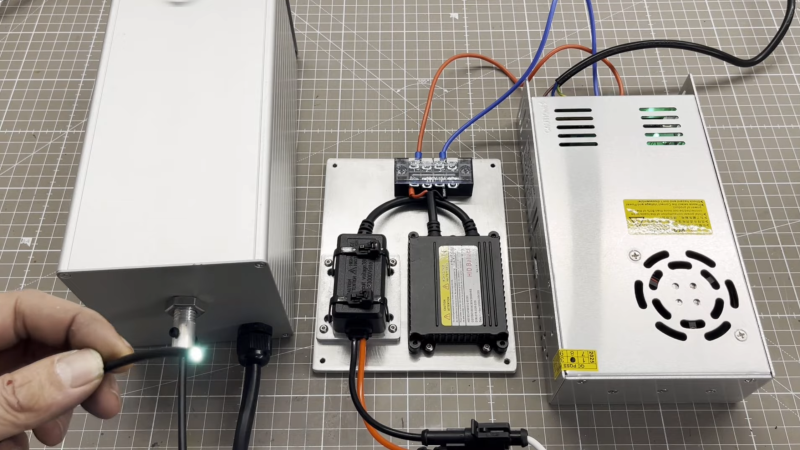
An aluminium box is visible on the left side of the image, with a power supply on the right side, and a lamp ballast in the middle. A man's hand is holding the end of an optical fiber in the lower left corner, and it is emitting a white light.

Building A Xenon Lamp For Spectroscopy

Before a spectrometer can do any useful work, it needs to be calibrated to identify wavelengths correctly. This is usually done by detecting several characteristic peaks or dips in a well-known light source and using these as a reference to identify other wavelengths. The most common reference for hobbyists is the pair of peaks produced by a mercury-vapor fluorescent light, but a more versatile option is a xenon-bulb light source, such as [Markus Bindhammer] made in his latest video.

A xenon gas discharge produces a wide band of wavelengths, which makes it a useful illumination source for absorbance spectroscopy. Even better, Xenon also has several characteristic spikes in the infrared region. For his light source, [Markus] used an H7 xenon bulb meant for a vehicle headlight. The bulb sits in the center of the source, with a concave mirror behind it and a pair of converging lenses in front of it. The converging lenses focus the light onto the end of an optical cable made of PMMA to better transmit UV. A few aluminum brackets hold all the parts in place. The concave mirror is made out of a cut-open section of aluminum pipe. The entire setup is mounted inside an aluminum case, with a fan on one end for cooling. To keep stray light out of the case, a light trap covers the fan’s outlet.

[Markus] hadn’t yet tested the light source with his unique spectrometer, but it looks as though it should work nicely. We’ve seen a wide variety of amateur spectrometers here, but it’s also illuminating to take a look at commercial scientific light sources.

Sending TOSLINK Wirelessly With Lasers

TOSLINK was developed in the early 1980s as a simple interface for sending digital audio over fiber optic cables, and  despite its age, is still featured on plenty of modern home entertainment devices. As demonstrated by [DIY Perks], this old tech can even be taught some new tricks — namely, transmitting surround sound wirelessly.

Often, a TOSLINK stream is transmitted with a simple LED. [DIY Perks] realized that the TOSLINK signal could instead be used to modulate a cheap red laser diode. This would allow the audio signal to be sent wirelessly through the open air for quite some distance, assuming you could accurately aim it at a TOSLINK receiver. The first test was successful, with the aid of a nifty trick, [DIY Perks] filled the open TOSLINK port with a translucent plastic diffuser to make a larger target to aim at.

The rest of the video demonstrates how this technique can be used for surround sound transmission without cables. [DIY Perks] whipped up a series of 3D printed ceiling mirror mounts that could tidily bounce laser light for each surround channel to each individual satellite speaker.

It’s a very innovative way to do surround sound. It’s not a complete solution to wiring issues—you still need a way to power each speaker. Ultimately, though, it’s a super cool way to run your home theater setup that will surely be a talking point when your guests notice the laser mirrors on the ceiling.

We’ve seen some other stealthy surround sound setups before, too.

Continue reading “Sending TOSLINK Wirelessly With Lasers”

Tearing Down A Mysteriously Cheap $5 Fiber Optic To Cable TV Adapter

In his regular browsing on AliExpress, [Ben Jeffrey] came across something he didn’t understand—a $5 fiber optic to RF cable TV adapter. It was excessively cheap, and even more mysteriously, this thing didn’t even need power. He had to know how it worked, so he bought one and got down to tinkering with it.

Inside the device in question.

[Ben] needed some hardware to test the device with, so he spent $77 on a RF-to-fiber converter and a cheap composite-to-RF modulator so he could test the $5 fiber-to-RF part. A grand expenditure to explore a $5 device, but a necessary sacrifice for the investigation. Once [Ben] hooked up a fiber optic signal to the converter, he was amazed to see it doing its job properly. It was converting the incoming video stream to RF, and it could readily be tuned in on a TV, where the video appeared clean and true.

It was disassembly that showed how simple these devices really are. Because they’re one-way converters, they simply need to convert a changing light signal into an RF signal. Inside the adapter is a photodiode which picks up the incoming light, and with the aid of a few passives, the current it generates from that light becomes the RF signal fed into the TV. There’s no need for a separate power source—the photodiode effectively works like a solar panel, getting the power from the incoming light itself. The part is ultimately cheap for one reason—there just isn’t that much to it!

It’s a neat look at something you might suspect is complex, but is actually very simple. We’ve explored other weird TV tech before, too, like the way Rediffusion used telephone lines to deliver video content. Video after the break.