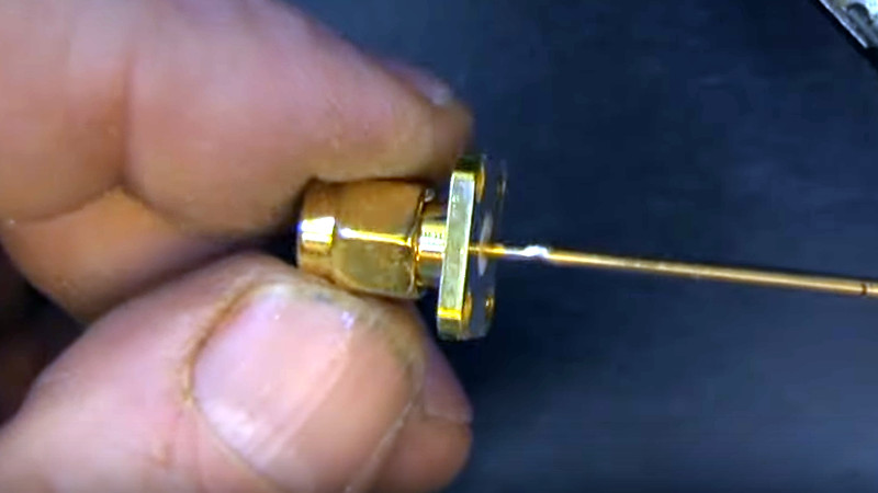
There’s a satisfaction in watching someone else at work, particularly when they are demonstrating a solution to a soldering problem you have encountered in the past. SMA panel sockets have a particularly tiny solder bucket on their reverse, and since they often need to be soldered onto brass rod as part of microwave antenna construction they present a soldering challenge. [Andrew McNeil] is here to help, with a foolproof method of achieving a joint that is both electrically and mechanically sound.
The best connections to a solder bucket come when the wire connected to it nestles within its circular center. If this doesn’t happen and a blob of solder merely encapsulates both wire and bucket, the mechanical strength of the solder blob alone is not usually sufficient. The brass rod is wider than the bucket, so he takes us through carefully grinding it down to the right diameter for the bucket so it sits in place and can have the solder sweated into the gap. The result is very quick and simple, but has that essential satisfaction we mentioned earlier. It’s a small hack, but if you’ve ever soldered to a too-small RF connector you’ll understand. For more fun and games with RF connectors, take a look at our overview.


Hmmm… So, basically the “hack” is: if you need to stick a stick into a hole, but it doesn’t fit then reduce the size of the stick.
That’s what SHE said!
Hmm, I put the brass rod in a lathe and use a stationary tool or stone. I also always put the mating part on to give it more rigidity and make it easier to hold / fasten somewhere when you are soldering.
Sure but this is probably for the non-machinists.
But your lathe doesn’t play cool music.
I just cut a point in it with a plier. Not as neat but very fast and no problems so far
is poor solder technique part of the hack too?
Hey, don’t you need to include a link to videos of your own soldering technique whenever you criticize someone else’s?
What are they soldering a piece of brazing rod to an SMA connector for? And what do you mean by “electrically sound”? I assume you don’t care about RF performance as that’s a huge discontinuity in the impedance of that signal path.
Helpful hint: if the wire doesn’t fit the RF connector, then you’re using the wrong connector and/or wire.
Did you bother to look at the video or even read the article?
The “wire” is actually the antenna element and, though I didn’t see it explicitly stated, the larger diameter yields increased bandwidth.
Then the title is wrong. It implies wiring sma connectors is tricky, and it will provide a technique. (I note people say the same thing avpbout BNC connectors).
Instead, this is about the “tricky job” of soldering an antenna to an sma connector.
Oh, come on, the title is accurate, and it’s at most 0.5 Benchoffs in hookosity. Thou doth protest too much.
I watched the video and read this article. After watching the video, I’m not inclined to follow up on their work as they’ve already made a large number of clear blunders. With the context of this being part of an antenna, I am even more shocked at the poor technique here. They’re using an SMA connector as a physical mount for an antenna element? That’s a horrible idea.
I’m familiar with the relationship between antenna element aspect ratio and bandwidth and I don’t see how it’s relevant here. If you’re bringing it up to justify connecting such large conductors to an SMA header, then I’ll take you back to this being a horrible mechanical configuration. Yes, the old “just solder some wire onto an SO-239 header” groundplane antenna design is a classic (classic bad idea). But, please stop repeating past mistakes.
You better not go looking inside any coax-waveguide transitions then: Connecting a monopole element directly to the connector is the standard technique used in right-angle transitions, available commercially from many vendors in SMA and N-type. Though it’s true doing this outdoors is dumb.
Gee, let me grab a waveguild transition… Hmm, there’s not a little dipole hanging in free space. There’s a dome of dialectric with a little antenna inside of it.
Of course we can’t see what you are looking at, so can only speculate what your “waveguild” is, or what your “dialectric” might be, but here’s a typical transition: http://microwaveeng.com/wp-content/uploads/2017/10/A80T9839-e1510082501382.jpg with TNC and N types. It has the big fat monopole (or half dipole if you prefer) element connected directly to the coax connector at top. The additional elements in there are tuning stubs.
Diagramatically, it’s as shown here: https://www.microwaves101.com/encyclopedias/waveguide-to-coax-transitions
If this is for microwave bands like the article mentioned, then the active element is probably not much more than a couple inches and would be part of a dish or waveguide, so I don’t see the issue with the SMA connector being used as a mounting element where there won’t be any fingerpoking.
This is also a really common technique for extremely small skew-planar or circular polarized antennas (2.4/5ghz) and for making antennas this has some ideas that could be carried forward to making different kinds of special purpose antennas or active elements.
Besides, when your entire antenna is less than 3″ how else would you suggest mounting it?
You are kinda fitting the stereotype of a cranky old ham rather than looking at this as someone figuring out and making something rather than just buying whatever is ‘good enough’.
I want my Dremel to sound like his. Maybe if I made a rotary tool from a DC motor and fed it with a Class C amplifier….
Haven’t you heard? Class E is all the rage these days.
RF into a motor?
No different from Class C in that respect. Both are narrowband and expect a tuned load, by definition. Just use a big enough inductor to get into the audio range.
Or dispense with the notion of tuning the output circuit and just call it PWM. Or Class D if you want to get fancy.
I enjoy Andrew McNeil’s Helical and Spiral Conical Antenna designs.
However, he is one who tends to go off on the “thermal” microwave effects as the only possible effect with no consideration for tuning into whatever the bioelectromagnetic molecular energy resonance or whatever “thermal” or more possibly if not a “thermal” minimalist effect, an RF Specific or Non-Thermal RF effect is going on with “health attacks” potential issues and concerns.
Having been earlier on researching the microwave assisted catalysis of reactions back in my pre-undergraduate years with a little dabbling with for my undergraduate research in organic synthesis… uhm… dude the industry grew and back then there were differences in products compared to classical reactions. Granted… didn’t develop into the super autosynthesizer molecular energy for the reactants bond reactions desired tuned RF source specific research like I thought was the way. Oh well… someone probably didn’t want me discussing that much back then and probably wanted to hostile take credit or divert attention from their systems wireless concealed assault weapons nefarious use.