
I got a relatively inexpensive 6040 CNC machine, and have been spending most weekends making the thing work, and then cutting stuff, learning the toolchain, and making subsequent improvements. Probably 90% of my machine time has been on making improvements. It’s not that the machine was bad — I got the version with ballscrews and a decently solid frame — but it’s that it somehow didn’t work together as a whole. It’s just an incredibly unbalanced design.
Let’s start with the spindle motor. It’s a 2.2 kW water-cooled beast that is capable of putting tons of work into a piece and spinning at very high speed. Yet to keep up with the high speed spindle, the motors that move it around would have to be capable of high speeds as well — it’s a feeds and speeds thing if you’re not a CNC geek. And they can’t. Instead, the stepper motors that came with the kit are designed for maximum force at low speeds. Which can make sense for some machines, but for one with a slightly flexible X-axis like this one, that’s wasted as well. The frame just can’t handle the low-end grunt that the motors are capable of, so it can’t take advantage of the spindle’s power either. The design is all over the place.
 Over the last two months’ of weekends, I’ve been going through this iterative procedure of asking “what is my limiting factor right now?”, working on fixing that thing up, running it some, and then asking the question again. And it’s a good general procedure, and I believe that it’s getting me to the machine I want at the minimum cost of time, money, and effort.
At first, it was the driver hardware/software with its emulated USB parallel port, so I swapped out the controller for an Arduino running GRBL, soldered directly to the DB-25 that comes out of the back. At least it can put out pulses fast enough to order the motors around, but they would still stall out at high speeds. Swapping the stepper motors out for a high-speed pair only cost me €40, which makes you wonder why they didn’t just put the right motors on in the first place. The machine now travels fast enough to make use of the high-speed spindle, and I’m flying through plywood and plastics without leaving burn marks. It’s a huge win for not much money.
The final frontier is taking big bites out of aluminum. The spindle can do it, but I fear I’m up against the frame’s rigidity on the X-axis. For whatever reason, they went with unsupported rods on the X, which are significantly more flexible than an axis that’s backed up by more metal. And this is where the limiting factor may actually be my time and patience, rather than money. I just can’t bear to disassemble and reassemble the thing again. So for now, it’s going to be small nibbles, taking advantage of the machine’s speed, if not yet the spindle’s full horsepower.
But it’s odd, because this machine is a bundle of good parts. It’s just that they haven’t been chosen to work together optimally; the frame doesn’t work with the stepper motors, which don’t work with the spindle. If they went through my procedure of saying “what’s the limiting factor?” they could have saved themselves €100 by just shipping it with a wimpier spindle, which would have been a balanced, if anemic, machine. Or they could have built it with the right motors for more speed. Or supported rails for more grunt. Or both!
I’ll never know why they quit optimizing their design when they did. Maybe they never got past the slow USB/parallel port speed? But I’m near the end of my path, and I can tell because the limiting ingredient isn’t a simple upgrade, or even mere money anymore, but my own willpower.
How can you tell when you’re at the top of a mountain in a dense fog? A step you take in any direction would lead you downhill. How can you tell when you’re satisfied with a project’s state? When you don’t have the need, or desire, to undertake the next most obvious improvement.


Try taking multiple shallow passes, instead of single big one when cutting. Much easier on the machine.
Yeah, that’s what I’m doing now, but one always wants to push it a little bit further, no?
And for the record, the thing is plenty stiff for wood, it’s just on alu where I need to skim or else it deflects up a little bit and chatters.
and where is the write up on the modding itself? That is something I would value.
Well, that would require too much work :)
This article is for outsourcing the decision on which part to wotk on next. Elliot is smart like that.
That’d be fun. I’m actually thinking of doing a stepper-motor in-depth.
It’s a tool, you optimize it to do a job. The next optimization or upgrade is scheduled when it can’t do the job.
Needs driven model doesn’t always apply to hobbies.
But define “do the job”?
If you have seriously limited machine time it might not be up to the job for you because you can’t wait around all day for it tickle its way down through the the part.. But it can produce the part you need just fine in the end…
Then there is doing the job well – that soft x in this case means it is bound to have worse surface finish than you’d like on harder materials, the very slow steppers it came with mean on the soft stuff you end up more burning than milling through, again poor finish. But the job could probably be considered done…
Really it always come down to striking that balance between its more effort than it is worth to make it better for the future, and the lets make it the best machine it can be so I don’t need to work round its weakness again..
For the maker of the tool it’s job is to make a profit.
But they used parts of unbalanced capability.
They could have evened things out by using a cheaper spindle. Since a buyer couldn’t make use of that speed in it’s stock configuration then at least in theory they could have still charged the same price and pocketed the difference. Or they could have beefed up the other parts to be on par with the spindle, had a more capable machine and so charged more for it.
By doing what they did their tool was not optimized for it’s job of making a profit.
It’s not too hard to understand why they spent more on the spindle. Noobs are sold on spindle power. What kind of motors did you end up going with?
Actually 2.2kw spindle is the way to go. In combination with the watercooling you will still have moderate torque in the 2-4k rpm range.
It _does_ seem to be a very nice motor. Quiet and reasonably strong. If only I could say the same for the super-crappy water pump they packaged with it. (Another pending upgrade…)
But 24,000 rpm is really too fast for anything I’ve done. 6,000 – 12,000 is about the right range.
I buy the marketing angle too — spindle power is one of those headline numbers that they seem to toss around, while you have to go digging to see actually how thick the rails that support the axis are. (I guess they end up being not stiff enough anyway, so…)
On the other hand the smaller model (CNC3020) has a terribly underrated “400W” (more like 40W) spindle.
I suspect the manufacturing thought process is different to yours..
Does a water cooled spindle give us a higher profits margin? If so, it gets one.
Will the customer immediately notice cheap steppers? If not, ship them cheap ones.
There will be zero interest in making a ‘good’ product
well, it depends. Designing for curb appeal works for (some) noobs, but it’s brand-death for more knowledgeable customers. Look at power tools. Consumer brands like Ryobi are chock-a-block with pretty overmolding and YAGNI doo -dads. Pro-oriented brands like Milwaukee or Makita rarely try such stunts.
(No offence intended to Ryobi loyalists, of course)
Aren’t they all ownedby the same Chinese company though?
Yeah. The manufacturers of these are surely not expecting repeat customers, let alone brand loyalty. Once you’re in that world, the rules change yet again…
Those Chinese CNC machines (6040, 4030, 3018, …) are all built to a price point – cheapest components that look good together and have specs that check ignorant consumers’ boxes. The Genmitsu 3018 has pathetically flexible gantry rails, for example. You can’t tell that from the pictures unless you have some experience with CNC machines. Take very thin cuts and maybe you will get something decent. Perhaps the most egregious example is the 15 Watt laser cutter – 15 Watts continuous for a few minutes, maybe. There really is little engineering going on – just assembly of available parts sourced from the lowest cost supplier. Anyone who has shopped on Alliexpress knows what that gets you. All those machines look the same with very minor differences.
It is no surprise that there are forums filled with people asking how to make them work. I have long maintained that the majority of those machines wind up unused because either the buyers decide they like CNC and get a bigger and better machine or get so frustrated they stop trying.
Meh, or your work with what you’ve got and find methods to make it work.
I’ve got a 3018. The x axis isn’t very rigid, and the spindle is underpowered, but (aside from the easily rectified lack of limit switches) the biggest issue turned out to be the crappy mills you get all over ebay. Swapping those out for some surplus professional ones made a huge difference.
Beyond that, the other big issue is that the design is lacking adjustment screws to square and tram it; I had to build something to do that, but it’s still labourious.
I’ve seen people pull off some pretty cool things with a 3018, but I’m not deluding myself that their results are plug-and-play. (None of it is.)
But the difference between the 4030/6040 machines and the 3018 are night and day in terms of solidity. I’m complaining about a little bit of pivot upwards b/c of the deflection of 24 mm diameter steel rods over a 40 cm span. Honestly, I should be happy. :) And as long as the endmills don’t break, I am.
I really, really wish more software engineers thought that way. Unfortunately feature creep, code bloat and endless ‘tweaking’ seem to be a way of life with many of them.
Amen. In my view though, (most) software development is not an engineering process at all, it has a distinct flow of it’s own. Had we had a different university building to start teaching that, we would probably have less over-engineering, unnecessary upfront design and crippling premature optimization.
Most effort put into improving software development processes in the last decades (Agile, Lean, etc.) revolves around building software differently than we build planes, roads or bridges.
“Most effort put into improving software development processes in the last decades (Agile, Lean, etc.) revolves around building software differently than we build planes, roads or bridges.”
Well if software was as hard to duplicate as planes, bridges, or roads, the process would more closely resemble their physical counterparts.
That’s true to a certain extent, but it’s that very lack of engineering discipline is a major part of the problem.
Engineers designing planes, bridges, roads, etc. don’t usually add features because they would be ‘cool’.
IIRC John C. Dvorak once wrote in a PC Mag article on the cost of software “I don’t care if you spent $50,000 developing this program. The second copy costs you $2. Convince my why it’s worth the price you’re asking.”
“Well if software was as hard to duplicate as planes, bridges, or roads…”
It isn’t as hard. It’s much harder.
The whole problem with the generation of very good, extremely high-quality software is completely summarized by your whole–cavalier–attitude, and I might add, the same attitude of the majority of the population–most of whom include all levels of management responsible for life-and-death situations. Everyone knows that software is easy, right? Everyone just knows that one can solve any problem with software; right?
Does “Boeing 747 Max” ring a bell?
Software ‘generation’ has no relation to, and unfortunately does not mean “Software Engineering“. It does NOT mean real programming, following the principles laid down years ago buy the likes of Edsger Djikstra, Donald Knuth, David Parnas, et al.
It means ‘coding’; it means ‘hacking’; it means using the latest ‘Agile’-type BS, and low-code or no-code generation. It does not mean ANY Q-A, or documentation.
REAL software design is very hard work. That makes it costly. That makes it impossible to find in any commercial setting, where the only thing that matters is to get something out the door, and as quickly as possible.
*************************************************************
From David L. Parnas–
“There are no standards for computer programmers and no group to certify them.” [Think about this one!]
“When someone builds a bridge, he uses engineers who have been certified as knowing what they are doing. Yet when someone builds you a software program, he has no similar certification, even though your safety may be just as dependent upon that software working as it is upon the bridge supporting your weight.”
This is gold. Thanks.
To be frank, I don’t think feature creep or code bloat is a fault of either the software engineers or the development process. It’s more likely a management issue, the ones in control of the spec demands something that is not rooted in market requirements, or some sales engineer will sell a feature before checking with the development department whether that is feasible within the project framework.
Endless tweaking is a universal engineering hurdle, though.
YAGNI + KISS
Stick to these and you’ll go far
OK, I’ll admit I knew what KISS was but had to look up what YAGNI meant (you ain’t gonna need it), a software concept to avoid feature creep.
Both very nice ideas, but good luck getting your software developers to stick to them :)
Try getting them to abandon all their ideas and concepts (especially ones that were the root of problems) when doing a complete rewrite for a new version.
For YEARS Netscape Navigator, then browsers derived from it such as Firefox, had a problem with forms on many sites where they would not submit. The browser would just sit there for ages before popping a BS error window “The document contains no data.”
Meanwhile, ANY non-Netscape/Mozilla browser would work with the same site, at the same time, on the same computer. The form would submit instantly.
Despite several “total rewrites” over the span of years, the problem persisted. Eventually they removed the error message but not the problem.
What it had to be was someone on the team was repeatedly re-creating some identical (and buggy) code each time. Wouldn’t matter if he or she didn’t reference any source from previous versions, they had the same buggy ideas and would put them in the new version.
The position of Netscape etc was the problem was all those sites with forms were the problem.
Uhhh, when your product is the only product exhibiting a problem, it’s your product, not all the websites no other browsers have issues working with.
The issue seems to be mostly fixed but still in recent versions of Firefox I’ve run into sites that have something that won’t work but it’s fine in Chrome or Edge, or back before IE was obsolete, no problem there either.
Agree 100% with both Ivan and Jonathan. Stick to these, and you’ll not go far wrong. Others don’t, which then makes you more valuable too. I’ve often told people that ‘a lazy engineer is a good engineer’. Some get it, some don’t.
Oh, I would say good luck getting management to stick to them.
“If we just sneak this little feature in the next sprint”, or “If we just do this a little bit in parallel”, “This is just a tiny tiny feature, shouldn’t be much work to add that” is in my experience typical statements from someone with decision-making authority, but a too high abstraction view of the project/product.
“It’s just 5 minutes typing.”
Sales guys. It doesn’t matter what SDLC model or release cycle you’re using, they’ll find a way to fuck it up for a commission.
Thank you for saving me the need to look up YAGNI
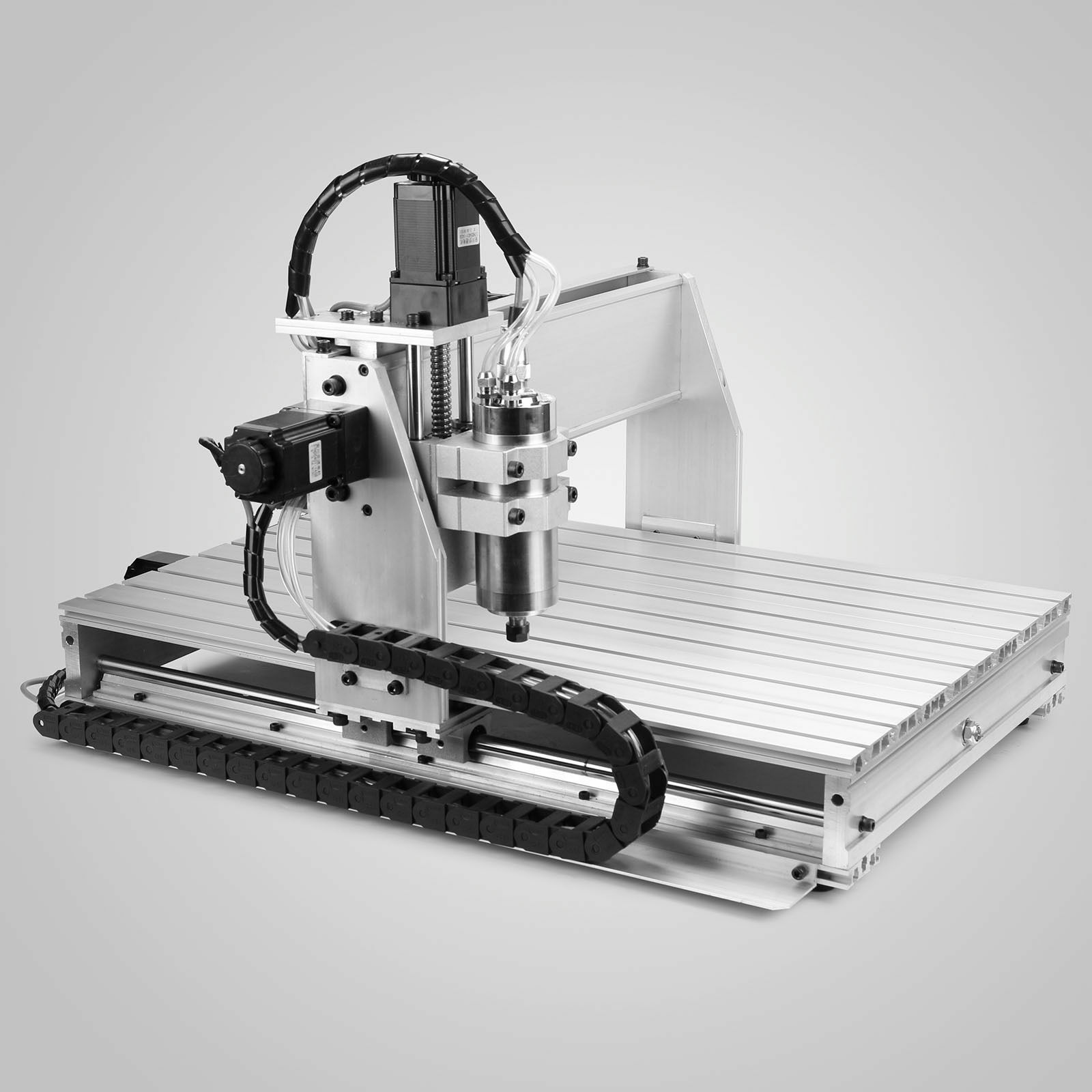
Oh the irony. In the fourth paragraph, the rhetorical question “what is my limiting factor right now?” appears. Beside this is a picture of what is presumably the machine in question. And the answer.
Somehow, with every project, the answer to that question always seems to be ‘everything’. And by everything, I mean that there is a never ending source of limiting factors just waiting in line to trip me up!
Actually the machine is not bad. What matters is what you want to use it for. I make 2 full set of rc car chassis on one 6040 cnc in about 2h. 1 sells for 200€. Limiting factor is spindle speed, end mill would love 60k RPM.
Honestly wouldn’t want to use a dmg for this. Profit would go into negative and parts would propably take even longer.
I have been eying these cheap CNC routers for some time myself.
But I have taken note of a few details I personally find very detractive in it.
The biggest issue is that the linear rails are only affixed to the work bench at the end, leaving them able to flex along the span. Same story for the bed itself. For lighter cuts, it likely doesn’t impact things much at all. But it still doesn’t instill confidence.
The second issue I find with them is their relatively tiny work height. Offering only a few cm of Z travel. Getting closer to 20-25cm would be much more convenient in a lot of hobby projects without it taking up tons more space.
So instead I have been designing on my own solution using a set of MGN12H rails more firmly attached along the work bed’s whole length. Where the two plates making up the sides of the gantry simply has some simple through holes for attaching the sliders/carriages riding the rails. And then through a simple off the shelf adapter attaching to a lead/ball screw. The rails in turn attach to a plate running along each side of the bed. (I am thinking of using some 10x50mm plates, to give 5cm of elevation up from the bed, and then provide the rest of the elevation via the gantry.)
Downside is that I intentionally designed it to have 2 lead/balls screws for x travel, one on each side of the gantry, something that does increase costs a bit. But the advantage is that the Z height can be made to suit any application one desires when building the machine itself. While still ensuring that X axis forces remains close to the where the forces from the tool happens to be. (Ie, we get less leverage compared to increasing the height of the gantry itself.)
My design is also not “ideal”, but for a small bench top CNC router I think it can be more suitable in a lot of cases.
I have a MaxNC that I used profitability to get my feet wet in the 90’s. Now that my needs are more stringent, I was looking at upgrading it. Bought some linear rails and screws, and looking at the frame decided I’d be better off starting from scratch; I’d end up replacing every component, every single piece of metal before getting where I wanted to be.
Then I did some designing, planning, and costing, and realized I’d be better off just buying a higher end machine.
I think that you’re right, in a sense. You can certainly design a better machine than what I got, and you can probably pull it off for not all that much more money.
Your two points, the unsupported X-axis rods and the unsupported bed, are right on. Because of the popularity of the format you can buy solid beds for €100 that bolt on. Retro-fitting supported rails shouldn’t be all that bad either. But sure, you could have saved some of that money by buying it right the first time.
And the Z has 70 mm of travel and 100 mm of clearance. You can play tricks with raising and lowering the spindle in its mount to accomodate some pieces, but b/c you always need as much clearance as you need plunge depth, you’re pretty much limited to ~30 mm relief. It’s more of a 2.5D machine. Still, you can mill out the 20 mm alu plate you need for your 20 cm-Z design. :)
I am currently cost estimating the idea, been doing it for a few months, looking at various solutions. I am not in a hurry per say.
Currently it is around 800-1000€ for the parts/materials. But then it has a 28x60cm bed and 20.4 cm Z clearance. And 15 cm z travel. (Considering vises and jigging, this is practically in the true 3D machining category.)
I have been thinking of milling some higher gantry sides for a 6040 unit, but since the main drive screw is underneath the bed, then the leverage posed onto the gantry by the cutting forces doesn’t really work in one’s favor.
The design I am working on has the drive screws a fair bit further up along the sides of the bed. And yes, chips spraying out over them is a concern that I need to solve with some containment shields to keep such chips on the bed. (thankfully plastic sheets are cheap and sufficiently sturdy.)
Though, if a factory in china decided to make a machine with this design, I would just buy it…
Bench top CNC routers/mills are fairly poorly designed in most cases, either being repurposed “flimsy” 3D printers, or shrunk down “bridgeport” clones that needs far more real-estate than a bench machine typically has room for, due to the bed facilitating the x & y axis.
In short, the gantry design handling X, Y and the Z axis is a very competent design for bench top machines thanks to keeping a small overall footprint compared to machine-able volume, and not needing to toss around the work piece itself during more rapid movements eliminating the need for a truly sturdy design. After all, a 1″ deep & wide cut isn’t really of interest in the bench top machining world.
How did you synchronize 2 separate ballscrews correctly? To my knowledge only company that uses dial ballscrew tech is Kitamura, and they licence it to Makino on some things I do believe.
Honestly- in professional mills, Z height often doesn’t get used as much as X & Y.
I’d love to see an article build series from someone going through all components and a basic design from scratch.
My thinking has always been figure out x & y you want, then go for near a cube in Z- and the size of your machine cube will dictate more the appropriate size of your spindle cartridge and tooling than anything picked arbitrarily, just for support issues of an oversized spindle, and the gage lenth of the toolholders it would take.
This in turn would dictate the mass you need to move, and you can choose linear rails accordingly based on the moment of inertial forces that would be needed to resist twisting in your design with that mass, for a standard 3 axis mill.
Though I’ve never seen anyone build a small horizontal cnc mill…
Synchronizing ball screws is technically something one can do with a stiff timing belt.
Yes, it won’t be super accurate, nor perfect. But as long as it is within needed tolerances it works.
If it wobbles back and forth or even skews a bit along its travel isn’t majorly important as long as it is sufficiently small.
One could take the other route of using 2 servos/steppers. For steppers one can just hook them up in parallel for better or worse… (Works fine as long as one doesn’t overpower the axis.) Using two drivers is though likely a more adept design, since then we can compensate for any skews imposed by the accuracy of our screws. Or even account for the skew caused by cutting forces, but this is likely overkill.
In regards to Z height.
Yes, most times it isn’t all that important in most milling machines. Mainly since one tends to have a fair bit of it.
But these bench top machines have fairly small Z height, so most of the projects I have in mind doesn’t fit under the gantry itself.
Though, I don’t know if the mill qualifies as a horizontal mill, since its spindle would still be vertical.
The good news is that once aligned for best squareness, the average axis positional accuracy will be no worse than a single ballscrew. In the digram below, two X ballscrews are shown with the space between them being traversed by the Y axis. If the requested X position is X, then each ballscrew will individually end up at X+/-tol, but the spindle will always remain in the plane defined by X+/-tol * Y. As long as the Y axis is long enough with respect to tol, the angular skew will be low enough that binding shouldn’t be an issue. The worst case skew would be tan A=2tol/Y. For two 600mm long C7 ballscrews with worst case positional accuracies of 50um/300mm, separated by 300mm of Y, you get A=tan-1(0.2/300), A=0.038 degrees.
+tol +tol
X X
-tol -tol
The bad news is those skews can create parts that are out-of-square, an error that should not exist for a single ballscrew solution. Let’s say that you’re cutting a 300mm * 300mm block, using the same C7 ballscrews in both X and Y. At both Y positions, 0mm and 300mm, those tolerances are in play, so the part could be anywhere from 299.9mm to 300.1mm in Y, but that dimension will be consistent wherever the spindle is in X. The same is true of a single ballscrew X axis, and you’ll end up with a part that is rectangular with square corners(*). When you have two ballscrews though, X is going to change with Y. You know that each X edge of the part will be between 299.8 mm and 300.2mm in length, but each Y edge could be skewed up to +/- 0.038 degrees. (That’s true of all features traversing Y.) You could end up with a square, a rectangle, a rhomboid, or a trapezoid.
You can avoid that error by using independent linear scales for positional feedback on each ballscrew, i.e. you’re only relying on the screw accuracy for movement, not positioning. Or you use a moving table gantry design that only requires one ballscrew. You can design a moving gantry system with only one ballscrew, but it needs a rigid-in-X beam moving under the table (which can reduce your range in X), and it’s difficult to keep the table rigid (because you need a void for that beam to travel in).
(*) Assuming that the X and Y rails are square to begin with, and that the machine frame is rigid, thermally stable etc, which rules out pretty much anything built from aluminium extrusion.
Horses for courses. If you want to cut wood (where +/- 0.5 mm is a tight tolerance), or hobby parts where most dimensions are non-critical, then the errors discussed likely don’t matter. If you’re looking for aerospace contracts or making molds though, you’ll be buying different machines.
Ugh, forgot that HaD mangles whitespace.
Yes, accuracy will technically never really be worse than a single ball screw.
Skew is a problem to contend with, but one can keep it in mind.
The out of squareness due to skew, I wouldn’t worry too much about.
Having the X and Y axis “perfectly” square to each other is already a challenge enough to get proper. Same for having the Y axis “perfectly” perpendicular to the setup. As long as it is square enough for the application it works. (Not that one has to go with bargain bin C7 screws for the X axis.)
In regards to having a central screw underneath the bed is something I think brings in more compromises than actual advantages. It makes the bed less rigid, it introduces more leverage on the gantry from cutting forces. One could place the screw on top of the gantry instead, but that introduces its own can of worms. In the end, I think a good bench top machine should strive towards having as much rigidity that it can achieve, ultra high precision were never the most important aspect in the design.
Your ending point that it largely depends on the end goal is the most important think to keep in mind.
A small bench top machine like this wouldn’t really be applicable in applications were exceptionally tight tolerances are needed. Though, for such cutting edge applications one wouldn’t be restricted to only being able to have a bench top machine built down to a price.
Agreed totally. I’d go to a moving table before a single-screw moving gantry. You could also reduce skew and associated squareness errors with higher grade ballscrews, but there’s a diminishing return. At some point external feedback becomes more cost effective.
Disclaimer: I very quickly scanned the article (extremely quickly, and the comments…not at all). This comment is the result of responding to the title ONLY as a result of being a working design engineer–a real engineer–all my life.
The answer to the title is exceedingly simple: one STOPS when the design meets the specs. Period.
I had one boss who would enforce reality with the simple admonition, “Now you’re starting to gold-plate it.”
I had another boss who, after a basic-functionality review of a design, would then take the design and personally work at removing components to make the design simpler (he was, himself, an extremely accomplished design engineer; the kind of engineering-design manager who probably doesn’t exist any more.).
“True engineering consists of not adding to a design, but removing.”–anon
While I agree in general, sometimes its worth gold plating…
And sometimes its worth making harder to make by any method other than the intended… So you don’t end up with the next set of contractors taking the general idea and riveting instead of welding, because they can do that cheaper (or anything else along those lines)…
Still sounds like you have had some damn good bosses though… Something I’ve never heard of in technical jobs, all my friends and most of their parents have all had business school bean counter bosses in their technical jobs of late, or had the job outsourced to India etc…
“…Something I’ve never heard of in technical jobs, all my friends and most of their parents have all had business school bean counter bosses in their technical jobs of late, or had the job outsourced to India etc…”
Exactly, precisely what’s wrong with the very sad state of the profession of engineering in the US, and probably, sadly, most of the world now.
What do you mean with high speed motors?
I’ve been building a machine from scratch, basically a 6mm aluminium version of the Sienci Mill One with Motedis style rollers on shaft rails and 8mm lead screws all around.
Too slow for the Kress spindle and too soft the rail bearings. Now a I’m fully rebuilding it with thicker aluminium, a mix of linear rails and sbr rails, ballscrews etc. And I’m sure it’s not the end…
One stops, when the initial base design doesn’t fulfill requirements.
Requirements
Grow over time. At the point of purchase they may have been different. And at low investment costs, requirements engineering is generally done “lightly”.
Base Design
It was good enough for purchase. Why niggle about it now? Or did you get a car with three instead of four wheels? Doesn’t sound like it.
The bundle
There is the product design and then there sourcing constraints. Hence there are products that are somehow skewed in features – fast and strong here, flimsy and weak there. Likely it’s where the supplier got a good deal on to keep the package price low.
Optimizing
It’s a journey. Looking at my 3DP… Yep, optimizing – but this Covid year was mainly about learning the production stack, materials, and secure/stable prints.
Overall it sounds like you have a great kit to learn on.
These mills will never be industry-grade.
>How can you tell when you’re at the top of a mountain in a dense fog? A step you take in any direction would lead you downhill.
One has to take a few steps further to discover that they’re not simply standing on a big rock.
We have the same kind of machine, changed the steppers for ac servo motors.
60st 600W ac servos are good, around $200 usd with driver and cables, just ask for longer cables, at least for the Z. IMO 3m is a little short. Usually the mounting holes are not the same as the stepper motor, we designed a holder for this.
Also go for a version with linear guide rails.
And for the limit switch we upgraded to Hall Effect Sensor Proximity Switch (1-2 usd each). With 3d printed holders.
Oh yeah, limit switches: I tapped and drilled holes and mounted some microswitches. The only thing notable about that is that I used shielded cable, b/c the endstop lines run through the same cable snake as the unshielded motor cables. Don’t know if it matters, but you hear horror stories, and I had shielded two-conductor on hand. I also run them NC, so they’re not floating around like antennas.
I don’t know the repeatability of the limit switches / homing procedure, though. I should measure that just for fun.
My stepper motor replacement was really just as simple as getting two steppers with similar torque but lower inductance so that they could run faster. Literally a €38 bill of materials, a week for delivery, and a one-evening bolt-on. I had to hack-saw-and-file the shafts to length so that I could re-use the mounting brackets and shaft couplers, but that was easy enough.
Thoughtful article, well done.
I don’t think you want to quit optimizing. You want to stop optimizing a failed design. I went through the same process with a cheap chinese cnc (based on the openbuilds OX). It used aluminium extrusions for all axes and belts and delrin rollers with M5 bolts as axles. It was a compliance mess and was even too spongy for hard wood. Especially plunges like drills.
I’ve mounted a 1.5KW spindle and it was much more capable than the rest of the machine, and I’ve modded it just like you to make it more rigid. But that only goes to a certain extend. The design was such that it was hard to reinforce the x axis to reduce torsion compliance.
So I designed a new one myself. Like you (maybe) I wasn’t going to make things too complicated and based the design on chinese pre assembled Z axes with linear rails and ball screws (used 2 for Y axis, 1 for X and 1 for Z). Since the back of the axes are extruded aluminium it it’s easy to screw in reinforcements like 20mm thick alu tooling plate and steel square tubing. The design is such that everything is easily modded. I abused the old cnc to make some parts to get the design going and finished the machine with its own capabilities. It’s now not only possible to make more aggressive alu cuts, but can cut mild steel and perhaps harder materials as well (haven’t tried). I like building machines so the design and building of this cnc was as much a goal as using it to make more machines :)
I use it for other things too of course. The odd art project, a ‘thank you’ plaque, bird house, speakers, small parts from aluminium, making cabinets (it’s 700x1500x200mm work area) etc.
A 100x100x3mm steel square tube really took care of torsion compliance on the x axis since the spindle sticks out under the gantry. The spindle is mounted on 20mm thick aluminium plate and the spindle itself is inside a motor length long aluminium extrusion (those square ones from aliexpress). I used shims instead of machining the square tube flat since I don’t have a surface grinder or mill.
As for the controller, I went with the AXBBE ethernet motion controller. You want real time devices taking care of critical timing. The included software is also very versatile and allows you to modify the entire interface. The controller strikes a nice balance between reliability, quality, functionality and ease of use. It can also be controlled using MACH3 or 4. It’s nice to have if the included software wasn’t going to ‘cut’ it.
Compared to the old chinese 8 bit controller, I could use speeds twice as fast without skipping a step (also due to ball screws vs poorly ratio’d pulley/belt pitch).