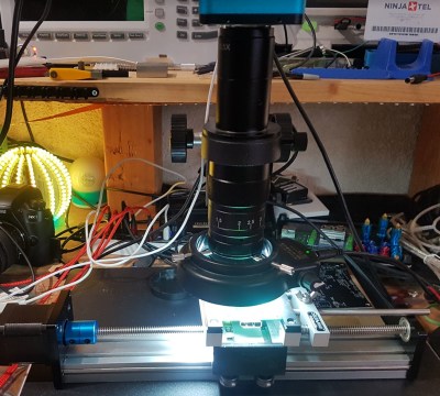
A desire for automated PCB inspection has led [charliex] down some deep rabbit holes. He’s written his own inspection software, he’s mounted his PCB vise on a stepper-controlled table, and now he’s hacked his digital microscope camera to allow remote and automated control.
Eakins cameras have become a relatively popular, relatively inexpensive choice for electronics hobbyists to inspect their small-scale work. The cameras have a USB port for a mouse and overlay a GUI on the HDMI output for controlling the camera’s various settings and capturing images to the SD card. Using the mouse-based GUI can feel clunky, though, so users have already endeavored to streamline the process to fit better in their workflow. [charliex] decided to take streamlining a few steps further.
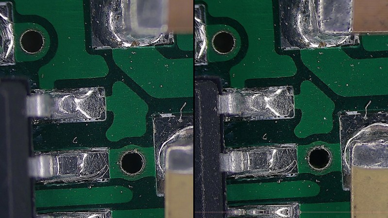
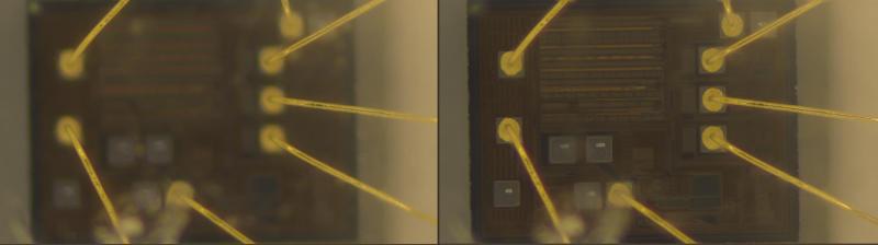
One issue in microscope photography is that microscopes have an extremely tight focus plane. So, even at the minuscule scales of an SMD circuit board, the components are simply too tall. Only a sub-millimeter-thick layer can be in focus at a time. If you take just a single image, much of what you want to see will be lost in the blurry distance. Focus stacking solves this problem by taking multiple pictures with the focus set at different depths then combining their focused bits into a single sharp image.
This takes care of the focus issue, but even the most streamlined and intuitive manual controls become tedious given the multitude of pictures required. So [charliex] searched for a way to remotely control his camera, automating focus stacking and possibly even full PCB scans.
He started off by cracking the inspection tool open and inspecting its innards. Inside, he found solder points for a serial interface and wired it up with his preferred scrap Samsung USB cable. The serial connection spat out a flurry of boot messages and immediately gave him a root shell into the Hi3516A IP Camera Linux SoC, so he got to work poking around to see how things run under the hood. Using strace to peek at the GUI process (which has the descriptive name myTest), he found it uses a local socket to communicate with a separate program, 3516a_proc, which actually controls the camera hardware via i2c. After capturing the signals for each of the GUI’s camera controls (focus, white balance, image capture, etc), it was just a matter of building, compiling, and uploading his own executable to replay those signals however he wanted.
The project’s GitHub repo has since been updated with a kernel module that supports a USB ethernet adapter, enabling [charliex] to take control of his camera over the network. However, the serial connection is still required initially to get those customizations loaded and running on the camera. He’s also made improvements to his vise table, introducing another dimension of movement, and has an Eagle schematic overlay working. This is a really fun and ongoing project, and we look forward to more updates. And if this still isn’t enough for your PCB inspection needs, you’ll probably have to reach beyond the visible spectrum.
Check out the quick video below to see the automatic focus stacking capture in action.


Wish I had time to make things like things. Sounds like a very interesting journey. Great work!
*this
Ah time.. the most valuable asset in human life, I too wish I had more of it so I can start working on the pile of personal project I have waiting for me :(
I just did something similar this weekend by strapping a cheap USB ‘microscope’ on a MP Select Mini v1 – http://funkboxing.com/wordpress/?p=2696
Mine is a pale imitation of this project but for $15 on eBay + junk I already had it was a pretty worthwhile.
This is awesome, actually. I have access a disused MP Select Mini that might just get the same treatment.