If you want a simple and easy introduction to stepper motors, check out the [IMSAI Guy]’s short video where he designs a very basic stepper motor controller and packs in a lot of quick lessons along the way. (Embedded below.)
He first goes over the fundamentals of a stepper motor in a practical, hands-on approach, and also shows us how to ring out the connections if the pinout is unknown. Next he demonstrates stepping the motor manually and then makes a simple FET driver circuit. Just when you’re expecting a small microcontroller to appear, the [IMSAI Guy] instead digs deep into his junk box and explains how to drive the motor with a 22V10 GAL (an electrically erasable PAL) and a 555 timer module. Based on a clearly-explained logic table for driving the coils, a sneaky way to introduce Karnaugh maps, he proceeds to write the output equations in WinCUPL.

WinCUPL is the modern version of CUPL (Compiler for Universal Programmable Logic) originally written by a company called Assisted Technology, now owned by Altium. CUPL and peers like PALASM from Monolithic Memories, Inc. (MMI) and ABEL from Data I/O Corporation were basic Hardware Description Languages specifically designed for PALs, GALs, and CPLDs. PALs were small arrays of logic gates with fusible interconnections, and your design is “burned” into the fuses much like a (EE)PROM. When designing with PALs, you could clearly visualize the connections in your mind, something that has since been remedied by the advent of modern FPGAs.
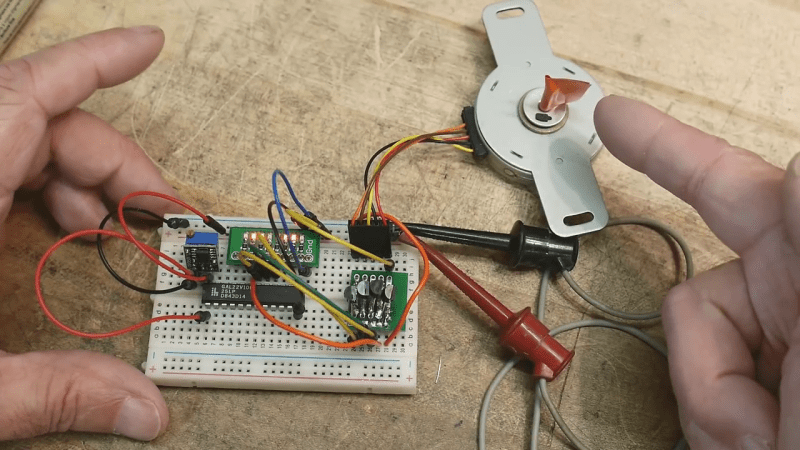
Alas, he cuts out the part where the source code is compiled and the 22V10 is programmed, and jumps directly into testing the circuit on a breadboard. Spoiler alert — it does work. Zooming in close and squinting, the nifty 555 timer breadboard module that he points out is called a TP353, which you can find from your favorite online supplier.
There is a lot to learn in this tutorial, and the [IMSAI Guy] does a great job at making the subject approachable to hobbyists and novices. We also covered another of his tutorials a couple of weeks ago on image sensors. Thanks to [itsevilbert] for the tip.


Hmm, nice idea,
Whats interesting is that with pass if time such as decades getting exposed to increasingly complex systems that it can be refreshing, cathartic and a reminder of conscious discipline to review the straightforward stuff intended mostly for a less experienced audience and although can be illuminating can offer meditative insights into combinatorial complexity as teaching opportunities back to the more complex…
Thanks
Hi Mike How’s the experiments with the “nootropic supplements” going? Still re re re re replicating results?
Just an errata, the module is the TZ353 not TP353.
Hmmm. That’s strange. I searched online for the TP353 and ordered a few myself from AliExpress. Maybe there are two flavors???
Uhm… maybe? I also read TP353 on the video but on ebay that code yield 0 results, but “TP353 555 circuit” showed me half a dozen TZ353… with TZ353 on the label
Maybe is a matter of everyone copying everyone else’s descriptions? There are minute layout differences but the circuit looks the same (a sample listing https://www.ebay.com/itm/TZ353-NE555-Square-wave-oscillator-Signal-Generator-Circuit-Module-Multivibrator/202148589106 )
Thanks, I had forgotten about the 22V10.
If programming is required, then it’s not a “hardware based” controller. There are some tricks which can make this even simpler.
Like a…. 555??
Well…
https://www.arduino.cc/en/uploads/Reference/unipolar_stepper_two_pins.png
The ULN2003 IC referenced there is just a bunch of Darlington pairs, basically a load of transistors that switch the output to ground when the corresponding input goes high. That circuit implements the same logic.
The two control inputs are in quadrature. That means you need to generate two square waves that are offset in phase by a quarter turn. I’m sure that could be arranged 555s, but it could also be an op-amp quadrature oscillator, or more interestingly: a rotary encoder with quadrature outputs. You turn the knob and the motor turns exactly the same number of clicks.
The selsyn motor lives!
My thought exactly. The first time I saw a pair running I was convinced it was some kind of trick. Magic, even. The best way to learn something is to figure out for yourself how the magic works.
Here it is. It’s a bit janky, but it works. Only a 555, some transistors and passives.
Falstad link:
https://tinyurl.com/yg4ny5z9
I made the circuit work with just a 555, one ULN2003, two transistors and some passives.
I posted the falstad shortlink, let’s see if it gets through the censorship.
Short description: 555 makes a 50:50 square wave, which goes to control input 1. The same signal is also taken to a low-pass filter which turns it into a triangle-ish wave, and a crude comparator made out of a NPN-PNP pair triggers for the upper half of the waveform, which produces a second square wave output for control input 2, shifted almost 90 degrees.
Because it’s not a perfect triangle wave, the phase shift is slightly less than 90 degrees, which makes the motor turn with a slight gallop. It also won’t start instantly, and can’t change direction – but this was an exercise in minimalism so we’ll allow that.
A proper voltage-controlled quadrature oscillator can be made with a quad op-amp IC and about ten passives – mostly resistors. It’s a little more complicated, but it has sharp transitions and perfect timing, so it avoids burning out the transistor buffer.
Strictly speaking no it’s not a solely hardware based controller, but using a GAL (gate array logic) is closer to implementing the driver using logic gate chips on a breadboard compared to only implementing software on a microcontroller. The only practical difference is you program the wiring between logic gates instead of physically plugging them into the breadboard. Claiming that alone makes this not a hardware based controller is just pedantry.
Counterpoint: if programming a gate array logic still counts as a hardware only solution, then programming an EPROM or flash memory does too, and therefore any microcontroller – after it has been programmed – is “hardware only”. Even if you add the arbitrary qualifier of “no CPU”, one can still implement a state machine with a ROM chip and a data latch – which does nothing without the data inside.
The point of a “hardware only” solution is that you put it together and it works instantly as it came out of the factory. No black boxes and secret magic incantations, no IDEs and compilers – a part already does what it does by its very nature instead of some missing bit that you have to add to it with a computer.
Counter counter point, you could technically flash chips using little more than a text file to assemble the microcode and bitbanging whatever programming interface. Your argument looks to me as similar to not having a datasheet for an ic and thus considering it a black box. There’s little difference in that situation to what you describe as black box/secret incantations in that without documentation “hardware only” chips are just as useless. There’s nothing holy about wiring things on a breadboard that makes them more magical than programming a part to do the same. I really don’t get people’s hate of embedded programming, compilers, etc.
That’s past the point though. You can technically program some old AVR chips by flipping switches by hand without a computer at all. Software is still software.
> similar to not having a datasheet for an ic
Not quite. It’s still going to work exactly the same as any other identical IC whether I have the datasheet or not – as long as there’s isn’t some program I need to add to it before it will function. That’s what I’m referring to. It needs a “secret incantation” to perform its function, and the part is a “black box” because you can’t know what it does by knowing what it is.
Also, I don’t hate embedded programming. I just like hardware based solutions more, because it has less of the Red Queen’s Race effect where everything you do is obsolete in five years, and you spend half your working hours updating software and learning how it breaks whatever you were doing last year.
Fair enough, I’ve had my fair share of fighting “bitrot” to get old libraries working again to understand how you feel. This happens more so with other people’s software though, I rarely dig up my own software and am at a complete loss as to how it works. I think problem is really not that software becomes obsolete but too many cooks in the kitchen. I just see hardware vs software implementation as different, not one being inherently better or worse than the other.
You don’t program an EPROM, instead you burn you program into an EPROM.
It’s not about how you get something into a chip, instead it’s about WHAT you have written and are putting into the chip.
Language is loose around this so just try to remember what a “program” actually is ie a set of instructions that are executed sequentially one at a time.
The code in a Hardware Definition Language has no instructions that execute at “runtime” and everything is in parallel not sequential execution.
If something can be simulated, emulated, synthesised or built with basic gates (or other components) WITHOUT any dependence on some “program” then it’s a hardware solution. It doesn’t matter if some “coding” was used along the way as long as it’s not a “runtime” program.
Again, it’s called an “Electrically Programmable Read Only Memory”.
>”a set of instructions that are executed sequentially one at a time. ”
Doesn’t have to be. They could be executed in parallel, in reverse order, interleaved… To “program” means simply to provide the instructions to a function – it does not concern with how those instructions are executed.
Besides, you’re trying to use a narrower definition of the word “to program” to make a point, when no such restriction was made in the first place.
>If something can be simulated, emulated, synthesised or built with basic gates (or other components) WITHOUT any dependence on some “program”
Yes, but the GAL is dependent on a program: It does not become functional without first programming it.
The difference we’re talking about here is like of a Compact Disc versus a CD-R. One comes out of the factory already pressed with the music, the other is a blank disc, and you have to “program” it to work like the other thing. This then implies you have a CD-R writer, a computer with suitable software, an internet connection to obtain the data, a license or ownership to the music… which is actually a heck of a lot more complicated than just having the CD with the music already on it.
People tend to forget this point when they’ve already put in the work of building the tools and learning the required programming skills and workflow. I might have to spend weeks and/or thousands of dollars in setting up and learning the ins and outs of programming a 22V10 GAL just to get the stupid motor turning.
Well the manufacturing process employs various stages of programming by your definition.
So what your saying is that nothing is a “hardware” solution unless it was made on a beach with a sand and smelter with not a computer in sight.
>Well the manufacturing process employs various stages of programming by your definition.
The difference here is whether the function of the component is fully defined at the time of its construction, or whether the device is left in a blank state to be programmed later. If it’s defined at the time of construction, then we don’t care, because we don’t have to program it.
ROMs are mask programed during manufacture. Does that make ROMs a hardware solution and not a software solution.
You don’t “program” the GAL. You use Hardware Definition Language which is not a program.
Splitting hairs, you effectively program it (ie compile and burn configuration to non-volatile memory)
The HDL defines the program, understood as a “set of instructions used to control the behavior of a machine”, which is then generated by the computer and programmed into the array.
Otherwise, why even call it a “Programmable Array Logic”, to which the GAL is merely an extension by being re-programmable.
It may be a Programmable Logic Array however you are not entering a “runtime” program.
With a CPU, you program what it has to DO.
With PAL, GAL, CPLD, FPGA you program what it has to BE. So there is no “runtime” program.
Yes, but that’s shifting the goalposts. You still program the GAL.
From the Title, I thought this would show me how to build a simple stepper.
No need for a 555. You can use the macrocell in the GAL for building RC or crystal oscillator just like you would with regular logic gates.
Yes, and you can even make the opamps by running gates in their linear region. But don’t tell new engineers that! They couldn’t stand the thought that digital ICs are made from analog components.
The digital part is easy to grasp. But stepper motors are very power hungry, and I remember having very hot resistors in my experiments. What I have not fully understood yet is the optimal way to drive a loaded stepper with good power efficiency. It would be great if someone can address this topic as well.
Define “loaded”.
There isn’t really any. Stepper motors are inherently inefficient. They use more or less constant power (I^2R loss) whether spinning or holding, and the only way not to is to turn the whole thing off.
If you want to make it use less energy, you need to employ some feedback mechanism that adjusts the amount of current going into the motor to match the amount of torque required by the load, at which point you are actually implementing a servomotor, and those you can already buy off the shelf.