“You could’ve done that with a 555 timer.” But what if all you have on hand is an ESP8266? [TechColab] needed to control a solenoid valve with a short pulse via a solid-state relay (SSR) but found that the trusty 555 timer was tricky to set properly. Additionally, they wanted to add features, such as fixed pulse length, that were difficult to implement—even with multiple timers. Still wanting to keep things cheap and accessible, [TechColab] has created the WiFive55, a 555 replacement based on the ESP-01 ESP8266 board.
[TechColab] began by investigating existing ESP-01 solid-state relay boards but found that many of them momentarily enable the output on startup—a risk [TechColab] deemed unacceptable. This was resolved in the WiFive55 by adding an RC filter to the SSR output, eliminating the output glitches at the cost of slowing switching time to around 20 ms—an acceptable trade for many SSR applications.
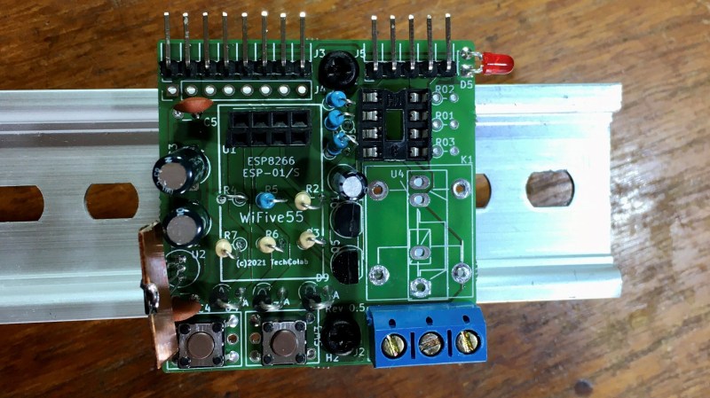
Since they were going to design a new PCB to support this improved ESP-01 SSR controller, [TechColab] decided to go all-out. To support loads of widely varying sizes, the PCB supports an optoisolator that switches up to 1 A, a MOSFET that switches up to 2 A, and an on-board relay or SSR that can switch up to 3 A. For heavy loads, it includes connections for an off-board SSR, which allow it to switch whatever current the SSR can handle (easily over 50 A). Because the ESP-01 is slightly more capable than the 555, the WiFive55 supports control via WiFi, GPIO, serial, and push-button. Keeping with the WiFive55’s original role as a 555 replacement, it even includes a header exposing a 555-like trigger and output interface!
We always like seeing inexpensive boards like the ESP-01 being used to their full potential, and we can’t wait to see what software [TechColab] cooks up for this! If you’re interested in getting started with the ESP-01, you might consider starting with this guide to blinking an LED over WiFi.


Calendar check. Nope, not April 1st. Okay then: this is the stupidest thing I’ve ever seen.
Just the same, it would be better with a RISC-V55.
I’m so confused!!
B^)
An esp32-c3 would do it. RISC-V core. And still has wifi.
My actual point is that “RISC-V” is pronounced as “risk five”, so that would be a “risk five fifty five”.
Happy to explain the joke.
Hahahaha, truer words were never uttered
No, it would have been better with an ESP-01 made of 555s…. it’s 555s all the way down, son.
^^^ this!
Yeah had to check that cal too cause who doesn’t have a 555 in their parts bin or maybe ten…. and nothing tricky about setting them up. It’s a very well understood beastie that uses very few external parts and has zero software bugs and also needs no usb or daughter boards etc and is very power flexible ie good chance you can ditch the dc to dc converter and voltage reg too. Hmmm
I have less than four 555 chips and only specified 1 in a design for a product. I have a huge junk pile of commercial boards, but rarely see a 555 on them. The last time they use a 555 or dervitative was in the old joystick interface on a PC and that went away after the ports were gone from sound cards.
I could have used a Schmitt trigger for a RC oscillator and save some of the ordering headache we had back then.
I’ve noticed the same thing. The 555 was used for the reset on the Apple II, and a 558 (sort of a quad 555, but not all the 555 pins brought out).
Maybe once I saw a 555 on a non-consumer piece of equipment.
That doesn’t negate using it, or negate using it instead of a complicated replacement, but it did surprise me that it didn’t see more use, given its longevity.
HackADay!
Keeping the 555 alive!
B^)
Having only gotten into making electronics recently, I don’t have them floating around yet. I’m incorporating one in my next design, but only to not worry about programming another IC.555s cost more than basic SOT23 ATTinys on Mouser right now, and if you want one in a smaller package such as SOT23 you’re looking at twice the price of. The ATTiny will also require fewer passives, and no thought to passive selection. Yeah, you’re looking at programming another MCU, but with an extremely simple task.
I have a few in a bin but I never use them. If I’m going to bother DIYing something, I’d rather spend the extra few dollars and give it WiFi.
555s seem more interesting for high volume production, but even then, most products can benefit from WiFi.
You really can do anything with enough 555s.
The folks spending a fortune on hundreds of 555s to avoid a $0.50 microcontroller are just afraid of learning new things.
If you try reading the article, the issue wasn’t the lack of 555s but the complexity of implementing the specific requirements with a 555. Instead of complaining about it, why don’t you take their design criteria and build a pure 555 implementation?
– fixed pulse length
– low on startup
– opto-isolated up to 1A (good luck with just a 555)
– switching up to 2A (Never seen a 555 rated for that)
– Wi-fi, serial, and button control
While you’re at it, explain why you’re using a device with a whole CPU in it, not just a handful of 555s. You might find the two problems are very closely related.
Good luck controlling/outputting that 1A from your microcontroller…. and from memory the 555 dont have the out high at power up issue either.
But wouldn’t a Cray supercomputer do the job just as well?
Oh yeah, just go and start a new comment meme…
The Bingo Board is FULL!
B^)
I’d kill for a thorough overview of switching inductive loads. Diodes, snubbers.
IIRC art of electornics is relatively terse, use a snubber if AC, use a diode if DC.
One of the TI app note shows how to pick a RC snubber for the diode in a switcher to prevent ringing. I have done the simulation using the app note’s advice to show the difference. There are app notes from others that show how to pick RC snubber for flyback etc.
Use a motor driver IC meant for both inductive and capacitive loads, that can current limit. If it’s a brushed motor you probably want a capacitor too.
The onboard diagnostics you get with those chips are too awesome to give up for discrete solutions.
Calling this a 555 replacement is a bit silly. The entire point of the 555 is that it’s a really simple circuit that’s good-enough ™ for many timing applications in electronics. This is just another case of substituting it with a microcontroller when more intricate timing control is necessary. Not the wrong path to go, since 555 spaghetti can make for a surprisingly good source of odd oscillations and instabilities.
But the “solution” to the start-up glitches in the description (an R-C filter) is not actually a proper solution because it limits the rise/fall time of the signals. What you usually do is simply place a fairly low value resistor (1-2 kOhm) to the supply rail or signal ground and just accept the slightly increased current consumption, because 1 – 3 mA extra on a 3.3V rail is easy enough to shrug off in most power applications. Most solutions to try to disable that current loss usually end up taking more current, so it’s not really worth bothering with.
Well for starters if you hold GPIO2 low during boot ESP8266s wont startup.
But overall a pull-up doesn’t seem much better than an RC if you ask me. Both might be the best solution depending on your needs.
10K pull-up on the GPIO, then a NPN configured as common emitter, with 1k collector resistor and 10k pull-down resistor between collector and ground…
Or use PIC10F or Attiny, both families have power-on reset and keep their pins in high impedance upon boot…
For starters, use another pin than GPIO2 for signals where the start-up state matters? You don’t *have* to use GPIO2 for that purpose, you can perfectly route it to another pin.
Most of the regular chips would have a well defined startup value documented in their user manual. It is up to the designers to pull the external pull up/down to default to a “safe” value until firmware catches up.
Failing that, one could use an external logic gate + power supply supervisor (with a programmable delay) to prevent those startup glitches. The logic gates let you select the right logic level until power is stabilized and whatever needed to be initialized before passing the signal as is.
that’s what i was thinking too. if it comes up high, then have high be the ‘off’ value. the idea of having a momentary wrong value during start up really rubs me the wrong way. you have to make it so the actual power-up value is the correct ‘neutral’ value, or the part is (imo) garbage.
i don’t know anything about the esp but i can imagine it coming up high, and then going low before user code gets a chance to do anything about it. so no matter how you engineer your output, it’s trying to screw you over, and you’re left with either a stupid hack (like the OP’s RC delay) or an overly smart (extra stupid) hack with extra logic components on the output.
i have no idea if the esp actually has that kind of limit but my experience with raspberry pi has really dented my enthusiasm for these sorts of components. it seems like the modern trend is for insanely bad products to dominate a corner of the hobbyist market. the frustrating part is that a better product wouldn’t take much more effort, it’s just that the peoople making the technical decisions have to have a better mindset. the volumes are high enough that it’s stupid for them to crank out so many units without involving someone with taste in the design phase.
thank god for stm32s, at least one cheap thing doesn’t suck.
grumble. kids these days, etc.
Both GPIO pins on ESP-01 have internal pull-ups, because these pins are used for selecting boot mode. Default is normal mode. Proper way to use this module is to add a simple inverter and pull-down for the SSR input…
Personally I’d use PIC10F20x or PIC10F32x. They use much less power than ESP-01, are easy to program in C, and even in assembly if one is desperate enough. And are relatively cheap, or at least used to be, when I last checked…
This is hilarious
B3 https://hackaday.io/project/176844-trollduino-v10
And B4
That trace that connected to the 2nd pin of the SSR (input) from the top passes by the 3rd pin (output) without sufficent creepage clearance. There are ample space that could be used for routing, but OP for some reason didn’t.
So verify before copy/pasting the routing!
Sorry make that the 4th pin instead of the 3rd. The trace is barely below the 4th pin when it exits towards the left. It could be done a lot better.
Which image are you looking at? Those are all 6 versions ago. Still working on SSR/RLA choice flexibility.
I used the board rules etc. to accommodate the expected DC & AC currents & voltages (with a conformal coating). That’s why I’ve said 3A not 10A like most of the similar boards on eBay. I’m happy to take feedback on the current version (see GitHub).
Whatever that get posted in HaD at the top of the page.
Not going to look at all 6 version of someone’s designs unless it has specific interest to me.
Clearance & capacity improved since then by turning the RLA/SSRs around & spreading edge components out a bit. Thanks for the feedback.
No 555? Just use a 12AU7.
It’s not that I didn’t have a 555 IC – I did & used it in a carrier board for the intended project.
But I couldn’t find a circuit hack to get a 555 to drop its output after the delay even if still triggered.
Setting one up is nothing tricky indeed. But doing so with multiple different parameters &
switching quickly between them is still not tricky but you can’t get an infinite-way switch.
The limited rise & fall times is not a problem as I don’t run mechanical relays at more than 5Hz.
And even as a child with my first digital watch, I couldn’t press the button any faster.
Though the board does have an RC bypass option if you don’t mind the boot-glitch.
Yes, the ESP-01 boot is woeful – but you can get them cheaper than many 555 suppliers.
Which is why I have more “ESP-01” (without pull-ups) & “ESP-01 S”s than I have 555s.
Don’t bother defending yourself, man. You built a great project.
The folks faulting you for not building a wi-fi interface out of 555s are people who’ve never designed a real device.