A microwave imaging setup. On the left is a monitor displaying a monochrome GUI. In the center is the RP2040-based positioning and measurement system, and on the right is a vector network analyzer.

Precise Positioning With The RP2040

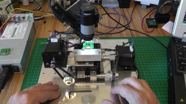
Microwave imaging is similar to CT imaging, but instead of X-rays, the microwaves are used to probe the structure and composition of an object. To facilitate experimentation with microwave imaging, [Zehao Li] and [Kapil Gangwar] developed a system based on the RP2040 to control the height and rotation of a test object.

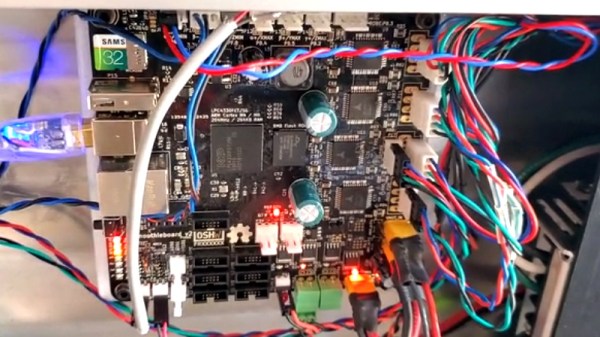
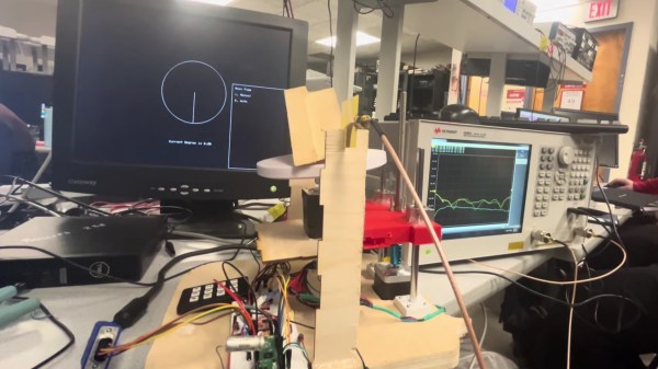
Their control system has a refreshingly physical user interface—a keypad. The keypad is used to configure the object’s position and the scanning step size, while user menus and the sample position are displayed in a clean and uncluttered interface over VGA. The RP2040 runs a multi-threaded program to handle user input, VGA display, and precise driving of two stepper motors for sample positioning.

The microwave imaging was performed by measuring the RF transmission over 2.5-8 GHz between two Vivaldi antennas on either side of the sample at a variety of angles. 2D cross-sections of the test object were reconstructed in Matlab using filtered back-projection. In this proof-of-concept demonstration, a commercial vector network analyzer was used to collect the data, but one could imagine migrating to a software defined radio (SDR) in the future.

A video demonstrating the system is embedded below the break. If you’re interested in DIY radio imaging, you might be interested in this guide to building your own synthetic aperture radar setup, or this analysis of an automotive radar chip.

Continue reading “Precise Positioning With The RP2040”

Minimal Tic Tac Toe Business Card

The PCB business card has long been a way for the aspiring electronics engineer to set themself apart from their peers. Handing out a card that is also a two player game is a great way to secure a couple minutes of a recruiter’s time, so [Ryan Chan] designed a business card that, in addition to his contact information, also has a complete Tic-Tac-Toe game built in.

[Ryan] decided that an OLED display was too expensive for something to hand out and an LED matrix too thick, so he decided to keep it simple and use an array of 18 LEDs—9 in each of two colors laid out in a familiar 3×3 grid. An ATmega328p running the Arduino bootloader serves as the brains of the operation. To achieve a truly minimal design [Ryan] uses a single SMD pushbutton for control: a short press moves your selection, a longer press finalizes your move, and a several-second press switches the game to a single-player mode, complete with AI.

If you’d like to design a Tic-Tac-Toe business card for yourself, [Ryan] was kind enough to upload the schematics and code for his card. If you’re still pondering what kind of PCB business card best represents you, it’s worth checking out cards with an updatable ePaper display or a tiny Tetris game.

Continue reading “Minimal Tic Tac Toe Business Card”

Photo of an automated plant watering system attached to four potted plants.

Automation Allows You To Leaf Your Plants Alone

The greatest threat to a potted plant stems from its owner’s forgetfulness, but [Sasa Karanovic] has created an automation system that will keep his plants from getting too thirsty. Over the past year [Sasa] has been documenting an elegant system for monitoring and watering plants which has now blossomed into a fully automated solution.

If you haven’t seen the earlier stages of the project, they’re definitely worth checking out. The short version is that [Sasa] has developed a watering system that uses I2C to communicate with soil moisture, temperature, and light sensors as well as to control solenoids that allow for individual plants to be watered as needed. An ESP32 serves as a bridge, allowing for the sensors to be read and the water to be dispensed via an HTTP interface.

In this final part, [Sasa] integrates his watering system into a home automation system. He uses a MySQL database to store logs of sensor data and watering activity, and n8n to automate measurement and watering. If something isn’t quite right, the system will even send him a Telegram notification that something is amiss.

If you think automation might be the best way to save your plants from a slow death, [Sasa] has kindly shared his excellent work on GitHub. Even if you don’t have a green thumb, this is still a great example of how to develop a home automation solution from scratch. If you’re more interested in television than gardening, check out [Sasa]’s approach to replacing a remote control with a web interface!

Continue reading “Automation Allows You To Leaf Your Plants Alone”

Photo of Pixel Pump Pick & Place Machine

Pixel Pump Pick & Place Positions Parts Precisely

You’ve finally decided to take the plunge and build a board with surface-mount parts. After carefully dispensing the solder paste with a syringe, it’s time to place the parts. You take up your trusty tweezers and reach to grab a SOIC-14 logic IC—only there’s not a great way to grab it. The IC is too long to grab one way and has leads obstructing the other. You work around the leads, drop the IC into place, and then pick up an 0402 resistor. You gently set the resistor into your perfectly dispensed solder paste, pull the tweezers away, and the resistor has stuck to your slightly magnetic tweezers. [Robin Reiter] realized that hobbyists and small manufacturers needed a better way to assemble their surface-mount designs, so he’s building the Pixel Pump Pick & Place, an open-source vacuum assembly tool.

Vacuum assembly tools use a blunt-tipped needle and suction to pick up surface-mount parts. Pressing an attached foot pedal disables the vacuum, allowing the part to be gently released. [Robin] thought to include a few thoughtful features to make the Pixel Pump even more useful. It has adjustable suction presets and a self-cleaning feature to blow out any solder paste you accidentally suck up. Most of the non-electronic parts are 3D printed, and [Robin] intends to make the entire design open-source.

[Robin] has a long history of designing tools to make surface-mount assembly easier—you may remember his 3D-printed magazines for dispensing surface-mount parts. If you want to take your PCB assembly setup to the next level, check out the PnPAssist, which shines a laser crosshair right where you should put each part.

Screenshot of debugging the Wokwi Arduino simulator

Digging Into An ATtiny Simulator Bug With GDB

Being able to track down a bug in a mountain of source code is a skill in its own right, and it’s a hard skill to learn from a book or online tutorial. Besides the trial-by-fire of learning while debugging your own project, the next best thing is to observe someone else’s process. [Uri Shaked] has given us a great opportunity to brush up on our debugging skills, as he demonstrates how to track down and squish a bug in the Wokwi Arduino simulator.

A user was kind enough to report the bug and include the offending Arduino sketch. [Uri]’s first step was to reduce the sketch to the smallest possible program that would still produce the bug.

Once a minimal program had been produced, it was time to check whether the problem was in one of the Arduino libraries or in the Wokwi simulator. [Uri] compiled the sketch, loaded it onto a ATtiny85, and compared the behavior of the simulator and the real thing. It turns out the code ran just fine on a physical ATtiny, so the problem must have been in the Arduino simulator itself.

To track down the bug in the simulator, [Uri] decided to break out the big gun—GDB. What follows is an excellent demonstration of how to use GDB to isolate a problem by examining the source code and using breakpoints and print statements. In the end, [Uri] managed to isolate the problem to a mis-placed bit in the simulation of the timer/counter interrupt flag register.

If you’d like to see more of [Uri]’s debugging prowess, check out his dive into an ATtiny’s write protection and configuration fuses. If you’ve been wowed by the power of GDB and want to learn more, check out this quick tutorial!

Continue reading “Digging Into An ATtiny Simulator Bug With GDB”

Using A Laser To Blast Away A Bayer Array

A Bayer array, or Bayer filter, is what lets a digital camera take color photos. It’s an array of tiny color filters that sit on top of a camera’s CCD. The filter makes it so that each sub-pixel in the image sensor only sees red, green, or blue light. The Bayer filter is an elegant tool that gives us color digital photos, but what would you do if you wanted to remove one?

[Les Wright] has devised a way to remove the Bayer filter from the Raspberry Pi Camera. Along with filtering red, green, and blue light for their respective sensors, Bayer filters also greatly reduce the amount of UV and IR light that make it to the CCD sensor. [Les] uses the Raspberry Pi camera in his Pi-based Spectrometer, and he wants to remove the Bayer filter to improve and expand its sensitivity.

Of course, [Les] isn’t the first one to want to do this. Some have succeeded in physically scratching the filter off of the CCD, but because the Pi Camera has vital circuitry around the outside of the sensor, scratching the filter off would likely destroy the circuitry. Others have stripped it off using chemical means, so [Les] gave this a go and destroyed no small number of cameras in his attempt to strip the filter off with solvents like DMSO, brake fluid, and industrial paint stripper.

A look at the CCD, halfway through the process.

Inspired by techniques used in industry, [Les] eventually tried to use a several-kW nitrogen laser to burn off the filter (which seems appropriate given his experience with lasers). He built a rig that raster scans the laser across the sensor using stepper motors to drive micrometer bases. A USB microscope was included to allow progress to be monitored, and you can see a change in the sensor’s appearance as the filter is removed.

After blasting off the Bayer filter, [Les] plugged his improved camera into his home-built spectrometer and pointed it outside. The new camera gives the spectrometer much more uniform sensitivity and allows [Les] to see further into the IR and UV bands. The spectrometer can even detect the Fraunhofer lines—subtle dips in the sun’s spectrum from absorption by molecules in the atmosphere.

This is incredible for a DIY setup and instrument, and we can’t wait to see what [Les] does next to improve his measurements. If your spectrometry needs are more mass than visual, take a look at this home-built mass spectrometer. Home spectrometers aren’t just for examining light spectra—they can also be used to judge the ripeness of fruit!

Continue reading “Using A Laser To Blast Away A Bayer Array”

Tales From The Global Chip Shortage: Smoothieboard

The semiconductor shortage sparked by the pandemic is showing no signs of slowing down. Although auto manufacturers were some of the first affected, the shortage has now spread and is impacting all sorts of projects, including the Smoothieboard open-source CNC controllers.

[Chris Cecil] walks through the production woes they’ve had over the last few months. It began this spring with a batch of the V1.1 boards. The prices of some of their chips started jumping, and then they were informed that the microcontroller that serves as the brains of the Smoothieboard was only available for five times the old price. In the end, they placed a smaller order, and V1.1 Smoothieboards will likely be scarce until the microcontroller’s price returns to normal.

Getting V2 of the boards into production has been even more difficult. Just weeks before the final prototype, it was discovered that the LPC4330 microcontroller the V2 was built around was also sold out worldwide. With the shortage in mind, a hole was left in the layout of the final version of V2 so that they could finish the design around whatever microcontroller they were able to get. In the end, they were able to lock down a supply of STM32H745 controllers, which are actually substantially more capable than the original device.

If you’re interested in the origins of the chip shortage, this article from January is a good place to start. This isn’t the first time parts shortages have wreaked havoc on the world of electronics—does anyone remember the global resistor shortage of ’18?