[Matti Airas] wanted to have a better electronics platform for making his boat smarter, more connected, and safer. He found traditional marine electronics expensive and not suited for hacking and tinkering. There was also the issue of lack of interoperability between device generations from the same supplier and between different brands. This led him to design the Sailor Hat with ESP32 — a marine specific, open source hardware development board.
Applications include all kinds of sensor and control interfaces for the boat, such as measurement of fuel or water level, engine RPM, anchoring chain length counter, or setting up smart lighting or smart refrigeration control. The board is designed to work with the traditional NMEA 2000 standard, as well as with Signal K. NMEA 2000 is standardized as IEC 61162-3, but isn’t open source or free. Signal K, on the other hand, is free and open source, and can co-exist alongside NMEA 2000.
The marine environment can be pretty harsh with extremes of temperature, rain, humidity, condensation and vibration. Boats, just like automobiles, have a notoriously noisy electrical environment and [Matti] has paid special attention to noise and surge suppression throughout the board. The board can work with either 12 V or 24 V bus systems since the on board DC-DC converter is rated up to 32 V input. Connections between the board and the outside world need to be very robust, so it is designed to accept various types of connectors depending on how robust you want it to be.
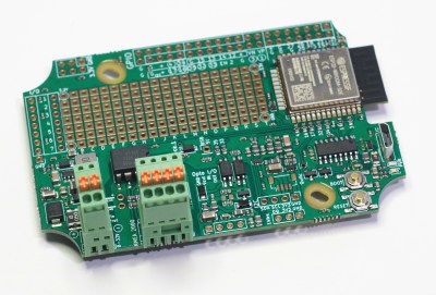 The Sailor Hat is based around a standard ESP32-WROOM-32 module. Interfaces include a CAN bus transceiver, opto-coupled input and output, I2C, 1-wire and QWIIC interfaces, USB Micro-B programming conector, plus a couple of buttons and LEDs. All of the ESP32 GPIO pins are terminated on a GPIO header, with jumper options to disable terminations to the standard interfaces and instead route them to the GPIO header as needed. Additionally, there’s a generous prototyping area to add additional hardware to the board. Hardware design files are hosted on the project repository on GitHub.
On the software side, there are several frameworks that can be used, with PlatformIO, SensESP, ESPHome and Visual Studio Code being the recommended choices. Or you could use any of the widely available SDK’s for the ESP32 platform — Espressif SDK, Arduino Core for ESP32, MicroPython, NodeMCU or Rust.
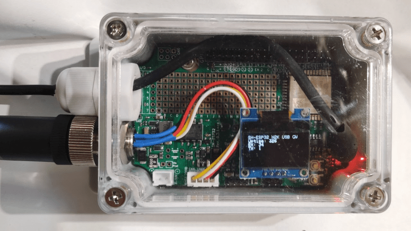
[Matti]’s NMEA 2000 USB gateway example is a good way to get a grip on hardware assembly and software installation required to build a practical project using the Sailor Hat. The board is designed to withstand a harsh electrical environment. But it’s mechanical installation obviously requires greater care if it has to survive marine applications. The Sailor Hat can be installed in commonly available, 100x68x50 mm or larger plastic waterproof enclosures, rated for IP65 or higher. The bulkhead connectors and cable glands also need to be appropriately rated, and the enclosure may possibly need a IP68 rated ventilation plug to take care of environmental cycling within the enclosure.


Extra points for building arum level sensor.
Big issue for me is converting the old analog instruments to a NMEA format. For a twin engine boat converting, RPM, pool, temp, low oil pressure, etcis very pricey.
For RPM, I’ve recently read about someone who used a standard dollarstore bicycle computer to give an RPM readout.
The bicycle computers use a magnet attached to one of the wheels combined with a magnet sensor attached to the front fork to sense the RPM, this combined with the wheel diameter is used to calculate your speed.
This genius decided to glue the magnet to (iirc) his flywheel, and made a delightfully thrifty bracket to hold the sensor next to it.
In this case they used a calculator and a conversion formula to revert the speed readout back to RPM, an added benefit was that the bicycle computer could also automatically store ‘time cycled’, in this case this generated a neat way to check the engine run time.
It should be trivial to instead make a similar sensor that is readable by microcontroller, all you have to do is measure how often a magnet passes by a sensor. This would avoid the annoying manual speed conversion.
Aliexpress has a sensor convertor for about $95 (dual engine support). Looks like a relatively inexpensive way to upgrade a legacy system to N2K.
Link: https://www.aliexpress.com/item/1005001420470241.html?spm=a2g0o.productlist.0.0.33bd13a0hqjWj1&algo_pvid=cf330ec7-b819-4055-98cf-1176be90ec5e&algo_expid=cf330ec7-b819-4055-98cf-1176be90ec5e-1&btsid=0b0a556816194432013054337e887f&ws_ab_test=searchweb0_0,searchweb201602_,searchweb201603_
Points removed for saying “hacking and tinkering”. Is “hacking” different than “tinkering”? Can’t you just say “customizing”?
Shouldn’t a sailor’s cap be called a “gob”?
If only the documentation on the sensesp website was actually complete and worked and people could actually use esp32’s to talk to signalk
You are right. Nothing I have tried worked for me.