When the first Raspberry Pi rolled off the production line back in 2012 it sported a 26-pin expansion header that seemed to conceal endless possibilities. A later upgrade to the 40-pin header we have today unleashed a few more precious interfaces, but even then it’s still possible to run out. This was the problem faced by [woj], who needed a PWM line to drive a cooling fan but whose other work had used everything on the header. The solution? Dive into the other connectors on board looking for an unused GPIO.
Every full-sized Pi has a connector for the camera and the LCD screen, and to operate some of the functions of those peripherals they contain a few extra GPIOs that aren’t normally used by end users. If the camera or LCD is not being used then these lines are potentially up for grabs. In particular there’s a GPIO that turns the camera on or off that’s relatively easy to solder a wire to, and it was this one that fed the PWM line.
There are of course a few other ways to find some more lines on a Pi and indeed almost any microcontroller, with one of the many types of GPIO expansion chips. This trick is a particularly simple one though. and perhaps unsurprisingly it has surfaced here before.


That’s quite cool, how long before there’s an expansion HAT which breaks these out on headers via ribbon cables?
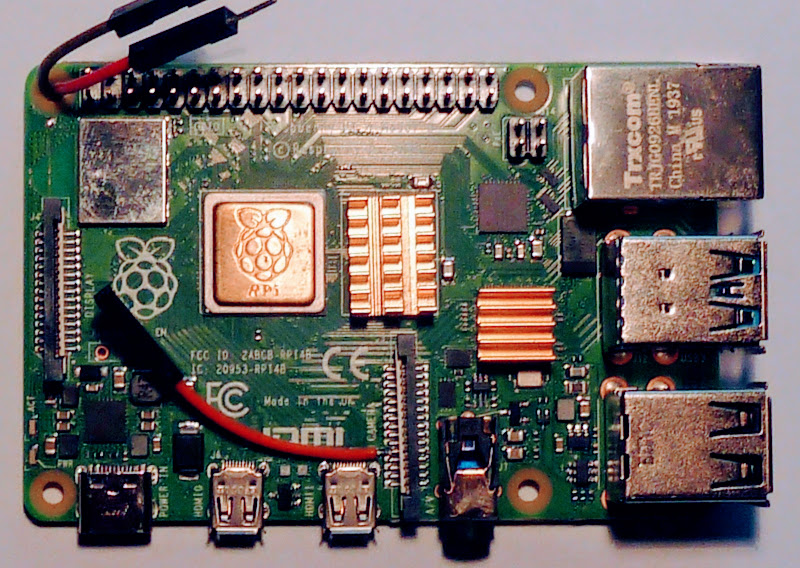
Also, what’s with the custom CPU heat spreader?
I was thinking the same. I have several pi B, 3B and 4B’s, (need to find a 2B somehow) and have never seen this die cover.
Hey, watch this everyone, is it a bird ? Is it a plane ? No, it’s Superchips league. Who are they ? “Octuplicator Twins”, code name: 74 ls 299 and 74 ls 595
The “Particularly Connected Family”, code name: PCF8074F, PCF8074AF, PCF8591 with his cousin TDA8444, PCF8583 (it work with I2C pins of GPIO header)
The “Shifter Act”, code name: 74 hc 541 with both pins “o.e.”(output enable) driven by a 4017 (a 74 ls 299 work too)
And there’s more to come…
Don’t worry dude, there’s plenty of stuff on the web to add pins on the GPIO…
Well yeah, multiplexers and co. are common. This is still a neat trick, and doesn’t need chips to be bought. As the saying goes, sometimes the best tool is often the one you already have.
The HAT idea to break them out may seem silly, but if it works just as well then why not? It seems to be more than enough for the needs of the person who did it. I love this idea simply because it’s a new solution to an old problem, and not one I’ve seen before. That, to me, makes it far more interesting than multiplexers.
I don’t think that i talk about multiplexers, because if i would, i’ll say something like 4051, 4052 and 4053 which are multiplexers.
Thanks Colton, I’D READ this article before comment, so please keep your words for another time, you’ll be nice…
Read but not understood. Or maybe you just missed the last paragraph.
Nope, not at all, that’s nice from you both to think because i’m french i can’t understand everything i read in english, that’s delicious.
Not only i’d read AND understood what was wrote, but i just let some components references to provide some of these ways, no more, no less.
So what about tell me directly what i done wrong (if i really screw something (but i don’t think that’s the case)) instead of playing “guess what i think about your comment ?” ?
I was also thinking shift registers and multiplexers. But somehow this is also a nice hack. Good to know the options.
Probably will never be a hat. It wouldn’t sell better than a simple IO expander using something like I2C or even a 74xx series mux. Those people willing to pay for more GPIOs won’t generally go halfway to save $0.50 on a board, they’ll get the one with the best supported/most used chip to be sure it already works in software. A specialized board that reclaims unused GPIO pins would cost about the same as one that adds a lot more than that and has better performance/support.
Is there a way to connect 75 or more momentary switches to one, and be able to read from one closed to all closed simultaneously?
Define simultaneously. Do you mean within a nanosecond? Then no. Within a millisecond, definitely. You can do it with an I/O expander, or a bunch of parallel-in-serial-out-shift registers, only using a handful or so GPIO.
I want to modernize an old bingo flashboard to eliminate the 28 volt incandescent bulbs that cost over $2 each and keep burning out. There are 75 of them for the numbers plus one for each row for the B I N G O letters which are always lit. The display is connected to the console by a large “hose” that has to have at least 77 wires in it. 1 ground, 1 + for the B I N G O, and 75 for the numbers.
It’s a brute force 1 to 1 wiring setup with a lever actuated microswitch in the board for each ball. When they’re drawn from the blower they’re placed into a matching numbered hole, closing the switch to illuminate the corresponding lamp.
The equipment is identical to this https://www.worthpoint.com/worthopedia/vintage-bingo-king-machine-automatic-308807258
I looked at white 28V LED bulbs. Wayyyy too costly, especially from the bingo equipment companies that have stuck to 28 volts for the lights for decades even after they started building solid state electronics with scads of TTL chips in the late 70’s. Makes for a simple cable between console and display and display boards can be daisy chained but the display and console are super complicated with multiple potential failure points (which the manuals detail how to troubleshoot). Their current models look like they haven’t changed electronic design much.
What I’d like to do is use something like one of the low end Arduinos in the display, which should have no problems running a string of 80 Neopixels, and connect it to the console with a USB or network cable.
The tricky part is being able to read all 75 ball switches as closed simultaneously, for the rare chance that all the balls get drawn before there’s a winner.
That would be fine for the basics. Nice-to-haves would be control for the other lights on the console (easy to do with the existing switches and wiring for them, just lower voltage for plain LEDs) and animations and color changes for the display board like having the last number called a different color and blinking the current number in another color. Then for a win do something like scroll BINGO across the display with changing colors. Could even do a retro mode with the Neopixel color and brightness adjusted to match the look of the old bulbs. Each game uses a different color for the cards so the BINGO letters’ colors could be changed to match, and for patterns that have columns out of play, turn those letters off.
Keyboard matrix with ‘ghosting’ diodes sounds like the go here. Unless you want to use i2c IO expansion devices….or daisy chain a chunk of 3-8 decoder devices and some fancy software encoding, or even shift registers maybe
You may not want to go this route, but if you have that many switches you could make a USB device with a microcontroller on the other end. Probably a little more expensive, but it may also suit your needs.
Shift registers my man, shift registers, lots of them.
Charlieplexing: 10 GPIO pins, 75 diodes 1N4148
PISO+SIPO: 6 GPIO pins, 1 PISO 74HC165, 2 SIPO 74HC595 (CMIIW)
I like the idea of controlling the fan speed with a python program. But how about wiring the transistor differently, so the fan runs full speed when the PWM control program hasn’t started yet or has crashed. Maybe a pullup to base is all you need for some extra safety?
This!!! There’s a reason why servers in a datacenter always start with the fans blowing air all over. It is not to pretend they’re a plane engine, people. You always design expecting the worse.
There are good plans and code on instuctables for doing just this. Google pi fan pwm .. or something along those lines and you’ll find it.
Not exactly an answer to the scenario discussed here, but if you have deep enough pockets you can hang a Mesa 7i94 and 8 x Mesa 7i71 on to the ethernet port and have 384 x 300mA / 32V power drivers at your disposal. (countless[1] other card combinations are possible, this is just one example)
Drivers might be a bit of a puzzle, though using the LinuxCNC Raspberry Pi SD card image and loading only the HAL layer is very much a possibility. At that point each pin is individually addressable from Python.
I am planning to use a similar combination on my current Pick-and-Place machine project.
[1] Countable, but I haven’t. I think that a maxed-out Pi could handle 2784 IO points. At that point, though, you would have $7000 in interface cards and the cheap, compact Pi would be looking a bit of a pointless choice.
HT16K33 and other matrix chips.
Most HaD projects are very wasteful on GPIO. Use them more efficiently and you won’t need to do this for most cases. There are lots of old tricks for time sharing GPIO on small microcontroller with limited GPIO.
Most interfaces have an enable/clock pin and when it it at a inactive state, you can use the rest of the GPIO lines doing other things. Multiplexed display, key matrix are effective ways of reducing I/O. I have reused the GPIO for column driver in a multiplexed display for polling buttons. Character LCD GPIO other than the Enable line can be time shared.
PWM??? Could have done that with a 555!
What? Somebody had to go there!
Personally i would just use I2C expandera that has individual PWM control for each output. Maybe something like this: CAT9532.