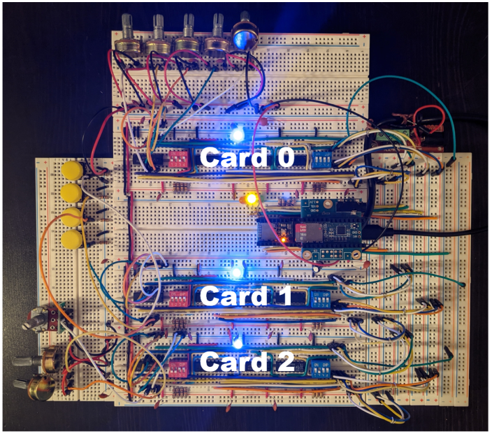
High school computer engineering teacher [Andy Birch] kept losing track of I/O pins on his home-built synth, so he made a custom plug and play addressable MUX system to solve the problem. [Andy]’s synth is based on the Teensy microcontroller, and he was already using CMOS analog 8:1 multiplexer chips (CD4051) to give him more I/O pins. But I/O pin expansion means that now there are more I/O pins to forget. Did I hook up that pitch potentiometer on U3 pin 13 or was it U10 pin 2?

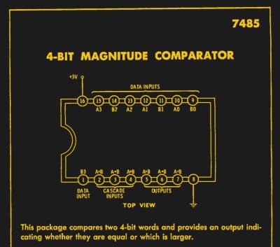
He proceeds to design an addressing system for each I/O card using three bits (expandable to four) supporting eight cards, with a maximum of 16 possible in the future. Since each card may not use all eight signals, each card can tell the Teensy how many signals it has. [Andy] does his address decoding on each card using OR and XOR gates. We would have considered using a single 74HC85 four-bit magnitude comparator instead. That would require only one chip instead of two, but would deprive his students of the opportunity to learn gate level address decoding.
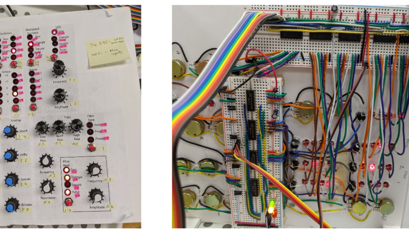
When seeing the term “I/O card”, you may be fooled like we were into thinking this was using PCBs and some kind of motherboard. [Andy]’s I/O cards are actually solderless breadboards mounted on the back of the synth control panel. We really like his bus technique — he removes the power strip sections from several breadboards and repurposes them as address and data buses. Check out the thorough documentation that [Andy] has prepared, and let us know if you have ever designed your own plug and play method for a project in the comments below.
[Ed Note: We love us some muxes!]


I want to go to Andy’s high school.
I love it when people do something like this to solve a “memory” problem.
Brilliant!
Awesome, Love it… I’m assembling Paia 9700 after I fix my old ARP Quadra and Axxe, so I admire your grass roots talent. Keep sharing