Worm gears are great if you have a low-speed, high-torque application in which you don’t need to backdrive. [Let’s Print] decided to see if they could print their own worm gear drives that would actually be usable in practice. The testing is enlightening for anyone looking to use 3D printed gearsets. (Video, embedded below.)
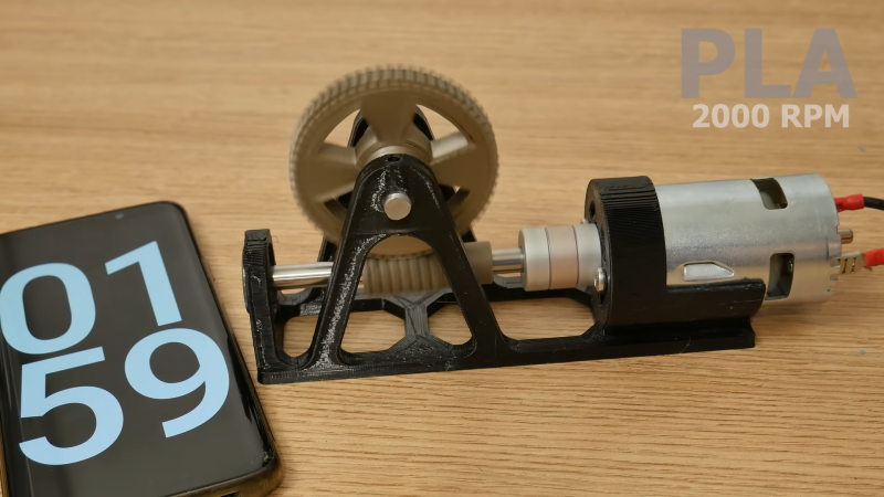
The testing involved printing worm gears on an FDM machine, in a variety of positions on the print bed in order to determine the impact of layer orientations on performance. Materials used were ABS, PLA and PETG. Testing conditions involved running a paired worm gear and worm wheel at various rotational speeds to determine if the plastic parts would heat up or otherwise fail when running.
The major upshot of the testing was that, unlubricated, gears in each material failed in under two minutes at 8,000 RPM. However, with adequate lubrication from a plastic-safe grease, each gearset was able to run for over ten minutes at 12,000 RPM. This makes sense, given the high friction typical in worm gear designs. However, it does bear noting that there was little to no load placed on the gear train. We’d love to see the testing done again with the drive doing some real work.
It also bears noting that worm drives typically don’t run at 12,000 RPM, but hey – it’s actually quite fun to watch. We’ve featured some 3D printed gearboxes before too, pulling off some impressive feats. Video after the break.


Would have been interesting to see how nylon fares without lube
Nice idea, but since the gears are used without load the results are of limited use.
Limited but not non-existent. Perhaps they could be used in a display of some sort. Maybe attach numbers to the wheel and place it behind a cutout so that only one number is visible at a time as the wheel turns.
Adding a load does sound like a great followup video to me.
Fine movement is nothing to be sneezed at.
It would be pretty unusual to have a worm and wheel made of the same material. Industrial gearboxes (David Brown Radicon, for example) use a bronze wheel and a steel worm. This is also the combination in the back axle of a 100+ year old vehicle that I occasionally drive, and that’s all-original and in perfect condition.
I think that a 3D-printed wheel using a short length of steel trapezoidal leadscrew might be a practical (and easy to manufacture) solution. The worm wheel would have to be generated with a 29 degree pressure angle, to match the leadscrew, but that should be a parameter in the design software.
29 degrees for ACME, 30 degrees for metric trapezoidal. Sorry.
Actually, half that as the pressure angle. Oh for an edit button.
Yeah, would be nice wouldn’t it. If its any consolation I got what you meant, it was nice and clear, and lets face it the angle of whatever thread you use is defining factor so putting a number on it upfront is irrelevant really.
The idea itself I like, lots of varieties of threaded rods you can select from based on scale and gear ratio desired. With the only real limitation being how small a feature you can 3d print/ the strength of those small teeth, so finer pitch threaded rods are probably out, but still lots of choice. I guess you can even 3d print oversized teeth anyway and then refine the teeth later with a file, the 3d printer would get you most of the way to the correct tooth profile, let you have cutouts in the wheel for lightness, so save you condiderable effort…
honestly, at small (<2mm) feature sizes, I highly doubt the difference between 29 and 30 degree pressure angle will be measurable in a printed Worm Drive Pinion, especially once it's had time to run-in
Thinking really small scale perhaps you don’t want teeth on the 3d print at all, just use the small threaded rod with an interference fit for some decent force right against a softer plastic fdm wheel – no need for features, and the threaded rod will either eventually “cut” (probably combination of wear and deform) its own teeth into that wheel gear or slowly mangle it. But either way should provide a pretty gearbox at any load sensible for such small scale parts for a while without any real complexity required.
You can make worm gear/wheel pairs even out of aluminum by taking a threaded steel rod and cutting a narrow slit into it with a dremel tool. When you press the spinning rod to a disc of aluminum, it will quickly eat its way around.
The difficulty is creating the exact right number of teeth on the wheel, because it will keep eating its way through and destroying the teeth you made as the wheel diameter shrinks. You have to know when to stop.
This is sometimes called free hobbing.
https://www.youtube.com/results?search_query=free+hobbing
But if you are already at the point of making worms and running stepper motors you can probably synch those motors and force the ratio to be correct.
>a bronze wheel and a steel worm
Essentially this combination is there to reduce friction with the bronze as the replacable wear item. The bronze get shaved down over time to better match the shape and/or mechanical fitting/tolerance of the stronger steel.
Also, to limit galling. In high pressure sliding applications some metals tend to microscopically transfer some of their surface material back and forth as they slide across the same type of metal, which eventually results in surface pitting, then friction, then destruction.
Because mother nature doesn’t like us to have nice things, two of two most common engineering metals, steel and aluminum, are especially prone. Aluminum, especially, can gall at surprisingly low forces.
This can be avoided by using dissimilar metals, or at least, minimized with carefully chosen alloy combinations and a lot of lubrication, which inhibits atomic bonding across surfaces.
it’s about the surface structure of the materials. Think of the surfaces as having a certain grain of sandpaper, if the other component, in this case a wheel, is of the same material you are going to get maximum engagement from the surface grain as the pits and troughs are at very similar spacing and thus the peaks in one component readily fall into the troughs in the other. The result is maximum friction and wear. Dissimilar materials have different size and spacing of this inherent “grain” and thus you wont get as much engagement and thus lower friction and wear.
Opens up any optical drive ever made yup nylon on nylon
Nylon is a great material for low-power gears, it has a usable surface finish right out of the mold (so you don’t have to hob gears out of bulk material) and it is surprisingly strong (McMaster says 11,000psi).
Also, kinda slippery, so low wear all around, and it plays nicely with a variety of long-lasting lubricants.
Listening at the sound it makes… something is very wrong from the beginning.
Sounds like a pepper grinder right out of the box :P
Agreed, in my experience (model trains) that grinding happens when the worm sits on the worm wheel directly rather than in the space between the teeth. This causes more friction until the gears are either bedded in or destroyed. Leaving a slight gap between the worm and wheel reduces that friction and will stop it vibrating as much as it does in the video. It also allows for lubrication which as we know was not used in the video.
>It also bears noting that worm drives typically don’t run at 12,000 RPM
Why not? Worm gear is a simple way to gives huge speed reduction + increase toque.
12,000rpm is what you would expect for unloaded speed of a small DC brush motor. They don’t have much torque, but speed is what you got. You would need to reduce the speed some how.
If you religion ask you to 3D print everything, you’ll have to deal with wear at high speed.
“If you[r] religion ask[s] you to 3D print everything…”
Obviously not everything is best made from plastic. But people keep pushing the boundaries of what can be 3d printed. I think it’s amazing how much has been accomplished so far. The true limits of what is possible can only be discovered by trying to go farther.
That might not mean much to someone with a fully decked out metalworking shop and decades of experience using it. Not everyone has the time, space, money, etc for that. But 3d printing is very accessible. Giving more people the ability to physically create the things they can imagine in their heads is not a bad thing.
If you see a design intended for printed plastic on the internet feel free to re-create it in metal, wood, ceramic, diamond or whatever your material of choice is. Maybe we will eventually be reading about it here even.
He forgot to test it under load. Should have fitted a pulley to the shaft of the output wheel, tied a string on this and winched up a weight. He would then have found that the steps and ridges inherent in 3D printing would start jamming when a large torque demand was made. Even though notionally (the motor’s stall torque) * (the worm gear’s ratio) >> mass*radius this would still occur. Planar involute and planetary type printed gearboxes don’t sufefr this type of jamming as all parts can be printed in the same plane.
Actually, 12,000 rpm is not unreasonable. Model railroad locomotives typically use worm gear drive. HO and larger engines typically use motors of about 10,000 rpm. N scale about 15,000. Brass worm and plastic gear is most common, but plastic/plastic is not unheard of.
I have printed a worm and gear to use on my Model Train to have a trigger for every quarter revolution of the drive wheels to trigger a puff of smoke and chuff sound. The gears are lubed and adjusted but they still test to wear out quickly, the worm more. I will look for this plastic grease and see if it helps. Great video test results.