Unable to account for the strange glitches he was seeing on his DIY CNC router, [Daniël Van Den Berg] wondered if his electronics might be suffering from some form of electromagnetic interference (EMI). So he did what any good hacker would do, and rummaged through the parts bin to build an impromptu EMI detector.
[Daniël] is quick to point out that he’s not an electrical engineer, and makes no guarantees about the accuracy of his tossed together gadget. But it does seem to work well enough in his testing that he’s able to identify particularly “noisy” electronic components, so it’s probably worth putting one together just to hear what your hardware is pumping into the environment.
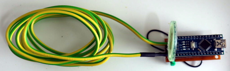
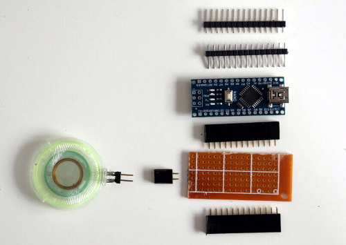 The hardware here is very simple, [Daniël] just attached a coil of solid copper wire to one of the analog pins on an Arduino Nano with a resistor, and hung a speaker off of one of the digital pins. From there, it just took a few lines of code to read the voltage in the coil and convert that into a tone for the speaker. The basic idea is that a strong alternating magnetic field will set up voltage fluctuations in the coil large enough for the Arduino’s ADC to read.
If you’re looking for a bit more insight into what kind of interference your electronic creations might be putting out, [Alex Whittimore] gave a fantastic presentation during the 2020 Hackaday Remoticon about performing RF debugging using a cheap RTL-SDR dongle.


…but did he find what was causing the glitches?
Exactly? Did he?
No stamina to get through 2 paragraphs, huh?
“he’s able to identify particularly “noisy” electronic components”
Having also read his blog page – there is no indication he has, so probably not.
It’s also unclear if his pickup coil is even telling him anything useful (given the size of the coil, the sensitivity of the ATMega inputs and the effective sample rate of running Arduino code).
One telling thing is on his blog page he states:
“However, there’s been some issues with the arduino randomly freezing, and end switches (wired as NO) randomly triggering. As it mostly seemed to happen when turning on the spindle,…”
If it’s specifically when the spindle turns on (rather than anytime when it’s running), then a better starting point would be checking the power supplies – it could well be dropping low enough that the end switches (that are probably normally pulled high and short-low on pressing) are giving the appearance of being read as ‘0’ by the uC.
I definitely did find that it was clever to move my controller board away from where I had it initially. I have seen less glitches since, but there’s always more work to be done :).
Add a diode and he has an AM receiver?
yeah that’s what i was thinking…i’ve seen this doodad before as just a non-selective AM receiver with a more traditional RF amplifier (i.e., all analog, not digital). but i’ve also never heard of it being used to track down a glitch like this, which as other people have pointed out is probably on power supply rails, not being broadcast through the air.
>The basic idea is that a strong alternating magnetic field will set up voltage fluctuations in the coil large enough for the Arduino’s ADC to read.
Yeah, but what you will hear depends on what the sampling frequency is relative to the noise frequency. For the basic arduino analog read function, I would not expect it to detect anything above a couple hundred hertz, which means you will only hear stray magnetic fields from AC motors, and not much else.
Hm, interesting thought. I have so far been able to find noises coming off of AC/DC converters and adapters, but it did surprise me that the noise from 230V lines was less loud than I expected (but it definitely and distinctly registered). I’ll have to dig into the sampling frequency a bit more then, to figure out if I can make it more effective.
I think you will detect it just fine but it’s frequency will be aliased down to a max of half your sampling rate.
Personally for connection between a VFD and the spindle I’ve moved to using double shielded cable (also called RVVP or RS485 PVC cable) with WS20 connector on one end and a GX20 connector on the other. Although it does require a bit of grinding with a dremmel of the plug to get the wire in due to the thickness of the pvc.
For the VFD itself I’ve put mine inside a grounded metal box to shield against noise leaking out and added a FN2080-10-06 filter between the input of the vfd and the mains input to prevent noise leaking out back down the mains
For the Motors I’m using CY single shielded cable with WS16 connectors (the WS connectors are like the GX aviation connectors but look cooler and feel a bit more rugged as they’re meant for IP67)
I too had noise caused by the spindle, though in my case the spindle is not electrically connected to the PC except via the 240 V outlet. I scoped the spindle-induced noise and it got worse as side load increased. Moving the spindle plug to an extension cable from a different outlet with a separate run back to the switchboard solved the issue for me.
EEVBlog had an episode about a diy EMI probe for a scope that might be of interest for a similar application.
I’m using an old AM transistor radio with loopstick antenna and LW for that purpose and added an AF input for external probes.
As the Atmel 328 sampling rate and input Z is all over the place, and unless the stuff is all near field and under several hundred kHz, dunno what is actually being ‘measured’. Anything over 100Hz is just being rectified and (unintentionally) integrated.
Have probably built over 100 sniffer probes for pre-compliance testing and for troubleshooting over last 30 years, so not hard to do if you use a little math and physics. And there are bazillions of published articles (would start with stuff from the IEEE EMC Society) on how to do this correctly.
If you are looking for broadband RF interference a cable toning probe with the headphone out plugged into a smart phone spectrum analyzer works great.
I have used this trick several times to track down “noises” in Hearing Loop systems in commercial settings. the frequency analyzer is nice as it not only give you a relative “how loud” but loud in this band. for most of my “hunts” I am usually seeing peaks in the 2.5Khz to 5Khz bands. These come from improperly grounded multi-pole motors in the HVAC system. Occasionally, I will also find switch mode power supplies (on other frequencies) with a neutral-ground or neutral-hot swapped.
In ancient and interesting times we measured the field strength of a magnet with a “snatch coil”. It looks like this could be easily adapted. https://www.toppr.com/ask/en-us/question/it-is-desired-to-measure-the-magnitude-of-field-between/
Some of the comments are ridiculous. This is hackaday not spend a thousand dollars on diagnostic equipment day. This is a very simple device, made entirely from spare parts to do a job, it works VERY well and it’s cool to boot. I made one, I used magnet wire for the coil and a 1meg resistor. I also added a flashing led for the hell of it. I made it so that the coil attaches with screw terminals so that I could experiment with different coils and different resistors easily. And let me tell you this thing is damn sensitive. It picks up motors, wifi, switching power supplies, mains. Basically anything with power flowing will get some kind of signal. Love the way the tones sound too. It’s a useful tool, a fun project to build and a neat toy. I for one am grateful that Daniel posted it. Thanks Daniel, it’s a great Idea and I hope you will post new things in the future. :)
Nice work! If you add a signal diode and capacitor to the pickup coil, you have a legit RF probe.