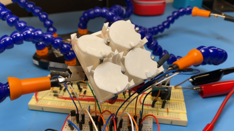
Displays have come a long way in the last few decades, but none can deliver the mesmerizing visual and audio experience of a large flip dot display. Both old panels and new panels can be expensive and difficult to source, so [Larry Builds] made his own flip dots with the help of 3D printing.
Flip dots are driven by a pair of electromagnetic posts that attract or repel a magnet embedded in the dot, and [Larry Builds] version is no different. For the electromagnets, he used M3 threaded rod with enamel wire wound around them using a drill. At first, he used a large magnet in the center of the 3D printed dot, but the magnetic field was large and strong enough to flip the surrounding dots in an array. He then changed the design to a small 4 mm diameter magnet in the edge that aligns directly with the electromagnets. This design looks very similar to those used by Breakfast for their massive installations. By modifying electromagnets and adding spacers around the magnets, he was able to reduce the operating current from 2 A to below 500 mA. [Larry Builds] also breadboarded a basic driver circuit consisting of H-bridges multiplexed to rows and columns with diodes.
We will be keeping a close eye on this project, and we look forward to seeing it evolve further. It’s definitely on our “things to build” list. We’ve embedded multiple videos after the break showing the progress thus far.
We’ve covered several interesting flip dot projects, including a water level indicator that doesn’t use any electronics and another that is crocheted.
Thanks for the tip [Baldpower]!


The problem with the magnets losing their magnetic field is the heat from the iron exceeding the Curie temp
That is at least mostly temporary, as is evidenced by older-style rice-cookers that use the curie temperature of magnets to trigger the end of cooking.
No, they use the Curie temperature of the adjacent ferromagnetic material. The magnet is carefully shrouded to keep it from getting too hot, because it will lose its magnetic field if it exceeds its Curie temperature.
There are types of magnets that have a curie temperature up over 250 C, so they don’t necessarily need to be insulated. These magnets are just weaker than the neodymium magnets we’re used to.
Nice ! another “dot flipper” ! https://hackaday.io/project/18541-dot-flippers
I had a similar idea as a kid but using dot matrix print heads. Had a blind friend and thought it would be an option so she could read the internet. I was 10 so never really pursued it.
What a wholesome comment :)
I think of the many ideas I had as a kid, and seeing them become real (even commercially successful) is truly inspiring.
Back in the late 90s I worked at a contract manufacturer which made AESCO “flapper signs”. They were huge panels which represented just one character on the display (300x500mm? IIRC).
Each letter had one magnetic coil which would drive a rod in/out to move the flap and around each coil was 4 LEDs on standoffs which barely allowed any lead protrusion.
Was a pretty interesting thing to work on but also very…very time consuming. At one point I was running wave solder, inline wash, touch up soldering and test on the boards so that we could free up extra people to hand place the coils and leds (think for a second how long it takes to put an led in a standoff, verify polarity and place it. Then do that over 200 times per board).
Here is a link I found which still supplies the parts for them http://fieldserviceamerica.com/junkyardsignparts/americanelectronicsign.html . I tried to find a pic of one of the signs in motion but I had no luck. The “SA flap module” at the bottom of the page is nearly identical to what I made (although I remember them as being 6×9 pixels).
I have a (broken?) SA FLAP MODULE DRIVER 601-10001 Rev 2 board that I don’t really know where to start debugging from. Do you have schematics around for these if they are similar to what you were building? I would appreciate the help!