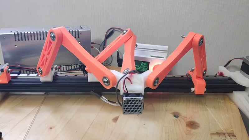
[JK Lee] has been experimenting with a monorail tripteron motion control system (video, embedded below) and trying to improve performance with varying tweaks to the design and with varying degrees of success. But [JK] is enjoying this project — he was inspired by an idea that maker [Nicholas Seward] proposed — building a tripteron on two rails (video), or even building one on a single rail (video). He is making good progress, most recently working on solving a vertical bounce issue. He is focusing on the middle arm, as this arm carries most of the weight. You can see a brief video explanation of the kinematics of the monorail tripteron that [JK] made (he warns us that English is not his native language, so focus on the equations and diagrams and not the grammar).
If you’re not familiar with the tripteron, it was conceived, along with the quadrupteron, at the Robotics Laboratory at Université Laval in Canada and patented by their researchers back in 2004. We wrote about an early implementation of a tripteron by [Apsu] back in 2016. These recent experiments, reducing the mechanism down to a single or double rail, are interesting.
Other than cool projects for makers like [Nicholas] and [JK] who enjoy tinkering, are there any applications of tripterons and/or quatrupterons in the real world? Let us know in the comments below. Thanks to [Littlejohn] for sending in the tip.


I’ve seen there’s at least one project trying to use this mechanism for a 3D printer.
The problem with ay multiple joint arm robotic mechanism is wobble at the end of the arm(s). That pretty much kills it for use in a 3D printer, unless you’re not concerned about print quality, If you look at industrial robots that don’t suffer from such problems, the bearings and cross sectional areas of the arms are large, and motor power is huge compared to the wimpy little things that hobbyists typically use. That adds mass and cost, both of which most 3D printing hobbyists are dead set against.
If the end of the arm wobbles, you can’t really use it to drill holes, pick and place components, extrude plastic, or do very much useful work.
It’s not entirely useless- there’s a lot to be learned about kinematics and programming for something like this that can probably be applied to other, more useful configurations, There might be some noncritical positioning applications.
Agree and add that there are going to be perpendicularity problems as the mass of the arms and the tool itself cause the arms to bend.
That bending won’t be uniform across the range of movement because when the first section of any arm is nearly vertical, bending will be minimal, but when the arm is more horizontal, bending will be greater. This applies to the second arm, too.
Not going to spend the time to try and figure out if the bending moments are the same for each arm section across total range (i.e. if the bending moment is always in the same plane for each arm section). If not, then the cross sections will need to be round or the Second moments will be different and compound the crazy different bending that will happen at different positions.
that’s where a high-repeatability bed probe comes into play
What would you do with that? Log data for every single position possible down to whatever tolerances you want to keep and somehow program your CAM to account for the change in perpendicularity of the axis of your tool to the work surface?
Go ahead and take 20k+ data points per square inch with your bed probe. Or you can take fewer data points and hope that you can find an extrapolation equation that will work, but you still won’t be accounting for the forces from the tool itself. No matter the tool you’re using, it will change the result.
CNC router? Perpendicularity will be tool-path dependent and will change with every single variable you can control.
3D printer? Will also probably be tool path dependent, to a lesser extent than the router.
Laser cutter? This is probably your second-best case scenario (best case being a pen plotter), but don’t use air assist and you’d better hope that the focus will be good over the whole range of movement.
Might work for gross motion for a pick and place with a second smaller more accuracy head providing compensation and accuracy?
Indeed, not tricky to do so for some applications, and anything closed loop that isn’t reliant on the kinematics for positioning (so using visual systems, time of flight sensors) won’t be bothered by the warping either…
For low consistent loads like in a 3d printer a calibration of the system will be able to correct for any warping of the beams and pivots as it moves anyway, so should still be pretty good as a printer option, and probably not terrible without either. Just need to make the right bits of it just heavy enough to keep it tensioned consistently, with good stiff beams – so perhaps carbon fibre/fibre glass reinforced 3d prints or profiles or even machined metals, decent bushing/bearing, stiff base rail, and accept it won’t run as fast as a delta can, nor be as consistent in its precision as a Cartesian. Should be great for long thin prints or mass production down a longer rail though.
And seems like a great pick and place to me only needing a rotational head and the suction gripper, you can make the rail as long as it needs to be to carry all the parts you need. Will only have to calibrate at the PCB height and your parts bins for any warping (and that’s assuming it really warps rather badly (which even this clearly rough prototype doesn’t seem to) as the required precision in surface mount part placement isn’t actually that high, the reflow process can fix pretty large errors there.)
It seems to me that the tool is going to wobble different amounts and at different frequencies depending on the arm positions and the speeds and accelerations applied. Even if you use an optical means to aim the tool, I don’t think correcting for the wobble is going to be easy unless it moves so slowly that the control loop can compensate in real time, but what resolution would you need in the camera if you were going to try to mill or 3D print an object? What advantage would all this complication have over a much simpler scheme that most FDM 3D printers already use?
It may well resonate differently in different positions – but if the whole thing is stiff enough those vibrations won’t matter much – everything resonates at some frequencies, its only the magnitude that really matters – and for 3d printing FDM style anyway it shouldn’t be hard to make that too small a variation to be noticed in the slightly imprecise mess of hot plastic extrusion of subtly varied diameter anyway.. Going to need to be constructed of stiffer materials than the ubiquitous Aluminium extrusion of course.
Don’t think it makes any sense whatsoever for something with high lateral tool forces – I’m sure you could still make this concept work, but it would be really hard.
On optical feedback the camera / point cloud from time of flight sensors need not be particularly huge as a data set, one thing that would vastly reduce that need is to put the camera on the tool head so its tracking patterns on the bed – it then knows easily how the two parallel lines of patterns are appearing to do the trig and know its orientation and position. Can get pretty impressive accuracy with that style even out of really rubbish webcam resolution.
I’m far from convinced this has any useful advantages over other designs, but in the right place it might. Perhaps along the wall behind the workbench – its got all the x travel you could ever need, but doesn’t take up the whole workbench, or even a meaningful amount of it when not in use. Nice big print area if used as an FDM, so would be good for repeating parts too.
The real challenge is the non-linearity of the resulting errors makes it incredibly difficult to correct for. You’ve observed that wobble can be reduced with appropriately stiff beams, bearings and motors. I’m going to add the base to that list too – that’s critical.
However, when we look at what “appropriately stiff” means in the context of the beams, we can conclude that since the angular presentations of the beams are unique to each position, the bending of those beams will be unique at each position too.
In the context of bearings, we’d need to select bearings that are equally stiff axially as they are radially. I’m not sure if such a thing exists. Angular contact bearings are designed to handle axial loads and radial loads, but I don’t know if any can be installed to be equally stiff in each.
When we consider the more traditional Cartesian machines, such as a typical moving table vertical mill, the stiffness of each axis beam is linear regardless of position. The linear bearings are usually loaded in the same direction for any given cutting force regardless of table position. (You can face some non-linearity by getting the center of gravity of the table outside of the bearings, but that is unusual.)
Remember that all the non-linearities stack. Each arm has three beams and four bearings. The result is that any ordinal Cartesian movement (other than X, where the beams just translate along the rail) sees the head move in a non-linear way, and whether cutting or laying down plastic, the surface finish will be impacted.
The real question: Is there an application where this geometry is more optimal than the more usual (Cartesian, polar) geometries? Also, what if we turn this thing on its end such that X becomes Y? Do the gravitational loads on the beams and bearings become more consistent? (Notwithstanding, we still have 3 beams and 4 bearings)
For simultaneous axial and radial loads you can use tapered roller bearings or bushings – often used in pairs on either side of a mounting point so they can be pre tensioned during the install which forces the tapers together firmly registering two parts in both dimensions.
In a situation like this though I don’t think the tapered type is needed at all normal tube bushings will work fine I would think. The motion is relatively slow (bushings don’t like fast much) and moving the carriage can be done with any size motor to bring the force up should there be too much friction (though most of that friction will likely be from the friction between the arms and the nuts that tighten them down, which will need to be fairly high if using none tapered bearing).
From the picture. The first thing I thought of was a fume extractor.
I’ve always been a big fan of Nick and his work with his students. He’s pretty consistently been at MRRF to show off new designs and they are always super fascinating. I even once just kind of wondered out-loud on G+ back when it was a thing, if delta arms needed to all be aligned with one another – and like 8 hours later, he had a youtube video up with a “wall delta” already simulated and moving. Lovely work Nick (if you see this) – grats on the Hackaday. You are awesome.
Aww shucks!!! Going to MRRF this year? I don’t think I will have much due to other obligation but I should have at least one new printer.
I think this could be used with a gripper to play chess or other board games where positioning of the pieces isn’t critical. It would certainly be interesting to watch it work. You could make a digital display type clock where the digits are changed by moving solid bars around with the robotic arm.
two very interesting applications where the arm-reach aspect plus tool planarity is a superior choice to something like a SCARA Arm or traditional multiaxial (N-Polar) arm – the entire arm can be much lighter than a N-Polar design unless it’s using cable or other remote mechanical drives which still add substantial weight to the end effector. It could probably be a good balance of speed and operational collision-box for the Chess-Bot idea as mentioned
Can we please not have very many (I’d prefer none) builds of patented stuff? The inventors chose their patent, we don’t have to give it free maker publicity. It’s a shame a cool maker project is already trapped in it, let’s not replicate that flaw by prompting additional builds.
That’d exclude a ton of very cool builds, such as this one. Even when not clear-cut, most builds include some aspect that is arguably patented, considering the trolly state of US patent law.
This isn’t covered by the Tripteron patent. Cheers!