We love to see LEDs combined in all shapes and sizes, so we were especially ticked when we caught a glimpse of [Debra Ansell]’s (also known as [GeekMomProjects]) interlocking triangular TriangleLightPanel system glowing on our screen. This unusually shaped array seemed to be self supporting and brightly glowing, so we had to know more. 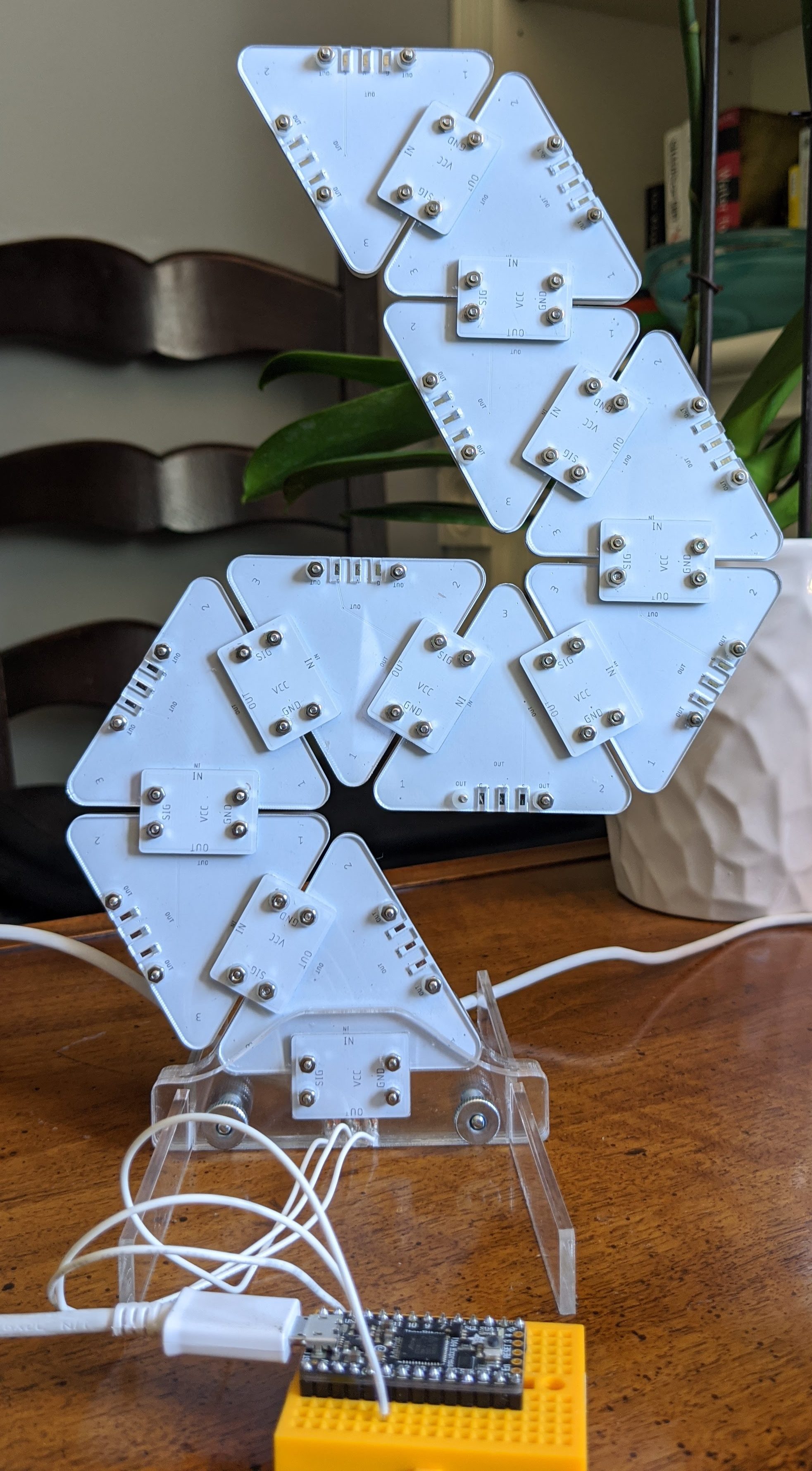
The TriangleLightPanel is a single, triangular, light panel (refreshing when everything is in the name, isn’t it?). Each panel consists of a single white PCBA holding three side-firing SK6812 LEDs aimed inward, covered by transparent acrylic. When the LEDs are doing their thing, the three-position arrangement and reflective PCB surface does diffuses the light sufficiently to illuminate each pane — if not perfectly evenly — very effectively. Given the simple construction it’s difficult to imagine how they could be significantly improved.
The real trick is the mechanical arrangement. Instead of being connected with classic Dupont jumper wires and 0.1″ headers or some sort of edge connector, [Debra] used spring contacts. But if you’re confused by the lack of edge-plated fingers think again; the connectors are simple plated strips on the back. There is a second PCBA which effectively acts as wires and a surface to mount the spring contacts on, which is bolted onto the back of the connected leaves to bridge between each node. The tiles need to be mechanically connected in any case, so it’s a brilliantly simple way to integrate the electrical connection with the necessary mechanical one.
All the requisite source files are available on the project’s GitHub page and the original Tweets announcing the project are here for reference. We can’t wait to see what this would look like with another 30 or 40 nodes! Enterprising hackers are already building their own setup; see [arturo182]’s 24 tile array glowing after the break.
Unfortunately, I ran out of screws and nuts, with 4 needed per leaf, they go faster than I anticipated. Ordering more soon 😅
Either way, my leaves are growing :) 🌿
(Powered by the RP2040 Stamp + Carrier) pic.twitter.com/rOWOojFnDa
— arturo182 (@arturo182) May 22, 2021


That is so very nice. Thank you GeekMom for a wonderful hacker class project.
Well this is very nice. I’ve seen the extremely expensive Nanoleaf modules around for a while and like the look but not the cost.
I would try to find some way to reduce the hot spots where the LEDs are, but I know that’s tricky.
I’d also add a different connector board that doesn’t connect the data lines, allowing the power to be distributed more easily, and make the physical structure a bit more stable.
In the twitter thread I see people talking about making it connect magnetically, but in my opinion that would only be helpful if each leaf could be auto-magically discovered somehow.
>if each leaf could be auto-magically discovered somehow.
add a 4. pin and a short-connector at the end of the chain between data in and the new 4. pin and check in software how many bits you have to clock in before it cames out again? Like JTAG.
“I would try to find some way to reduce the hot spots where the LEDs are”
perhaps an overlay shaded more at the corners than in the middle,
like take a picture of the module with LEDS at white at half power
bring it into photoshop, invert the picture and adjust brightness
use that image to make the template for the filter?
don’t know about transparent inks or dithering patterns, but perhaps someone with experience with that stuff can chime in too.
That’s pretty cool.
In response to other comments, I found myself wondering if something like these: (re: 2017 Queercon badge)
https://www.digikey.ca/en/products/detail/amphenol-icc-fci/10120045-400LF/4128730
-along with stronger back panel (maybe even with hermaphroditic bump¬ch pairs to mechanically protect the connectors) might allow some options.
I see there’s also a similar AMP/Tyco part, with a larger pitch, that increases the current capacity to 6A per position…
Having no parts on the back could allow an aluminum back plate, giving an option for some additional thermal dump, if the board was (re)designed to facilitate that.
In any case — thanks for giving the world your cool project to admire!
Whee!
-N
edit: no parts aside from connectors
Light diffusing hacks? Materials abound in a cracked screen backlit monitor or TV. Flat lenses to spread light out not up, and frosted and prismatic plastic layers of plastic sheets.Get ’em while they’re here, OLED will not have them.
Darned shame the connectors aren’t arranged to be symmetrical & identical: It is possible to connect them with reverse polarity. You need to pay attention to polarity when attaching them, and there are forbidden and impossible configurations. It would have been so easy to make them all identical and idiot-proof.
In this build it doesn’t matter because the voltage pin is in the middle of the three connector pins. Regardless of connector symmetry a tile’s input must be connected to the output of a previous tile to function. Even if the connection is reversed, voltage still connects to voltage and nothing bad happens other than the tile won’t light.
It’s easy to make the connectors completely agnostic to whether they are functioning as inputs or outputs, and impossible to get wrong. With six pins: Gnd|Vcc|in|out|Vcc|Gnd all three sides could be identical and you would not care about the orientation. If you use the screw connections as grounds you need just four pins for the Vcc and signal.
Yes, that’s pretty much true. This particular design couldn’t use the screws for connectors because the screws hold the acrylic to the board. The screw heads rest against the front acrylic layer and don’t have reliable contact with the triangular PCB. I also like to use nylon screws for my tile builds because they blend very nicely into the acrylic and barely show at all when illuminated.
It would be very easy, however, to add additional signal/voltage pins to the layout to create orientation independent connections. The only real downside is that it requires doubling the number of spring contacts per connector. Since you still have to keep the path of the signal in mind while laying out and connecting adjacent tiles, I was pretty aware of which side of each tile was input and output and I didn’t find it to be an issue. However your suggestion would save you the trouble of having to pay any attention whatsoever to tile orientation. Might be worth doing, depending on your priorities.
The connector board could still have 2 or 3 contacts on each side (power/support could have just 2), the tiles would just need 7 connection pads for symmetry. Gnd-v+-out-in-out-v+-gnd and connector boards having the only asymmetry. Trace routing on the tile would be a pain though.
7 will work, but 6 are sufficient.
And, since you’re using a bridge PCB to connect them, you can exploit the 2D array, so even just 4 is not hard. Or even just 3, if you can use the screw terminals as grounds.
3 in a line: in | Vcc | out (with ground through screws)
Or add a 4th for ground, in line but behind the Vcc one:
in | Vcc | out
| Gnd |
Yeah – once I sat down and thought about signal topology, I arrived at the same six-pin pattern that was indicated above. I tried a quick model of how this would work with the LED lighting connectors, similar to what the Queercon badge used, and it worked out pretty well.
The interesting conclusions I came to were:
– only two sides are ever populated with connectors, since the serial data path would have some issues with a branched path
– if done using a loopback block at the far end, there could be a calibration step, so that the ordering of the tiles becomes a software config
I could go into the gory details if anyone cares, but that’s where I ended up with a couple of quick doodles of power and signal routing and CAD models.
-N