If you’re looking for a quick and easy way to control a few devices from your computer, a cheap USB relay board might be the ideal solution. These are fairly simple gadgets, consisting of little more than a microcontroller and a handful of relays. But that doesn’t mean there isn’t room for improvement, and as [Michał Słomkowski] recently demonstrated, flashing these boards with a custom firmware allows the user to modify their default functionality.
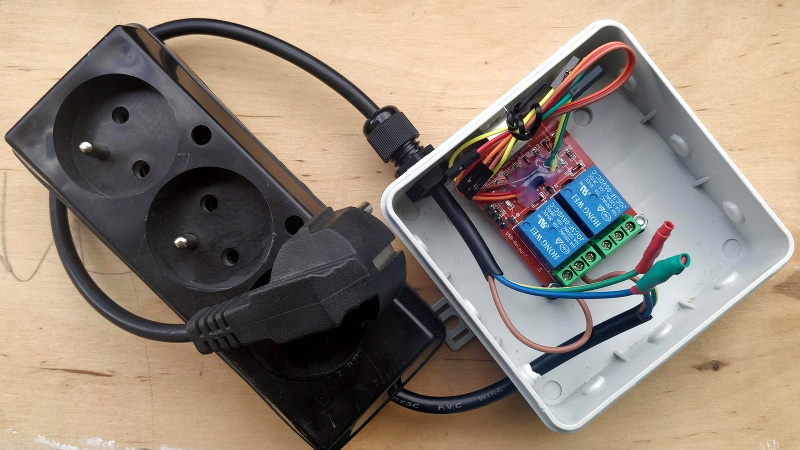
In his case, [Michał] wanted to build a power strip that would cut the power to any devices plugged into it once his computer went to sleep. Unfortunately, he couldn’t just check to see if there was 5 V on the line as his motherboard kept the USB ports powered up all the time. But with some modifications to the relay board’s firmware, he reasoned he should be able to detect if there was any USB activity by watching for the start-of-frame packet that goes out every millisecond when the bus is active.
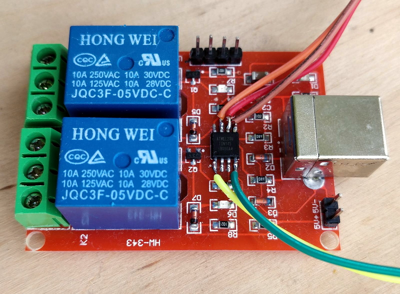
Now [Michał] isn’t claiming to be the first person to come up with a custom firmware for one of these boards, in fact, he credits an existing open source firmware project as an inspiration for his work. But he did create an entirely new GPLv3 firmware for these ATtiny45 powered devices, which includes among other improvements the latest version of V-USB. As it so happens, V-USB includes start-of-frame packet detection out of the box, which made it much easier to implement his activity detection code.
With the new firmware flashed to the relay board’s chip, [Michał] put it in an enclosure and wired up the outlets. But there was still one missing piece of the puzzle. It seems that Linux won’t actually send out the start-of-frame packets unless its actively communicating with a USB device, as part of the so-called “selective suspend” power saving feature. Luckily there is support for disabling this feature for specific devices based on their Vendor/Product ID pair, so after a little udev fiddling, everything was working as expected.
We love custom firmware projects here at Hackaday. Not only do they keep proprietary software out of our devices, but they often unlock new and expanded capabilities which otherwise would be hidden behind artificial paywalls.


So Michał decided that they were set up the Hong Wei and needed to be fixed?
I think you meant Wong Wei?
Or just go the faster route and tap off the +12v from the hard drive cable.
I butchered a USB extension cord and added it to the +5v rail and routed it out of the case through a grommet meant for external watercooling tubing.
But later added a automotive 0.5 amp fuse in series as a “at least I tried” safety measure.
That wiring job drives me nuts. He’s got 2 relays and 2 sockets, but runs both sockets off of one relay. I recognize there’s nothing wrong with that, but it sure seems like a missed opportunity. Just go ahead and wire it up, then if you decide to use the additional functionality in the future, you don’t have to rewire everything to make it happen. Future-proofing is for everyone!
Wouldn’t he then need a four core flex between the relay box and the plugboard?
Yes! He would! Now do it! ;)
Am I missing something? I can clearly see 3 sockets. Furthermore having taken apart some of these extension strips myself I can tell youv that it might just not be possible to wire each socket up individually. Some strips are made up of two copper busbars which do not only provide power but also hold the sockets contacts in place.
Oh, you’re right. I see the third now. That’s a good point about the bus bars, too. I suppose he’d need one of the power strips that has the individual switches on it. Then it becomes even more pointless. Alright, I take back my wiring comment.
Now what about the overly complicated method of activating the relay via USB frame packets? Why not just use one of the case fan power sockets? Case fans tend to run all the time and only when the computer is powered up.
Nope, that’s a dumb comment too. You need no more reason to hack than the love of hacking. I’ll see myself out.
Nothing wrong?
He uses 10A relays to drive sockets that are commonly rated for 16A. (Type E Plug/Socket handle 16A.)
The home electrical wiring for sockets is typically protected to at least supply 16A or 20A per circuit.
So in this setup it is possible perfectly possible to overload the 10A relay.
Sure it will work, and I’m sure you “promise” not to attach any heavy load to it, but this is exactly how electrical fires can start.
!!! If you use components that are not suited to handle the full potential current, you need to use an additional fuse to protect those components !!!
And this is even more important as most electrical circuits are not protected by a fuse that blows on over-current, but by a circuit breaker that switches of because of the heat generated by that current.
A 20A circuit breaker will allow much more than 20A for a short amount of time due to the thermal delays. (Think of a short-circuit situation.)
Author here, thank you for pointing out safety issues.
1) I doubt these Chinese relays would handle 10 A anyway. This setup supplies power to speakers, displays and won’t be conducting more than 200 W of power ever. But fuse sounds good, I may install 2 A in the future.
2) This very wall socket is protected by 10 A circuit breaker in breaker box. I replaced it with lower rating because I’m a bit scared of old commie installation with wires made of aluminum.
you should use the second relay to open the neutral, as it may be connected to the line from the wall. Otherwise, don’t consider your device unplugged and don’t open it while plugged in
You never EVER switch a neutral like that, unless it’s using a double pole relay that ensures both poles are always in the same state. Otherwise it’s a death trap. If the neutral relay were to malfunction allowing the hot wire to turn on with no neutral, then current flowing through the hot side will backfeed through all connected devices on the “dead” neutral and you could get zapped anyway from places you wouldn’t expect because they are supposed to be a grounded conductor. NOTHING is allowed to have an independently switched (meaning without mechanically interlocked common throw) neutral.
I’m not electrician myself, but I think this rule applies to fixed installations, where neutral and hot wires are clearly defined. But with 230 V plug, both wires can be hot since the plug is non-polarized. Majority of non-fixed devices like lamps, hairdryers etc have single pole switch.
You’re never supposed to touch anything inside electrical device before unplugging it from the wall socket anyway.