AM radios are relatively simple devices, and building one is a good way to start exploring the world of radio communications. [GreatScott] does exactly this in the video after the break, building both a transmitter and receiver.
At the most basic level, AM radio works by generating a carrier wave with an oscillator, and then modulating the amplitude with an audio signal. Around these parts, the venerable 555 timer is always brought up whenever things get to oscillating; so you’ll no doubt be happy to see [GreatScott] decided to give it a shot for his first experiments, testing two popular 555 transmitter circuits. One uses the control voltage pin to input the audio signal, while the other uses the reset pin. The CV-pin version worked slightly better, but it was still just barely possible to distinguish a voice over a standard commercial AM/FM receiver.
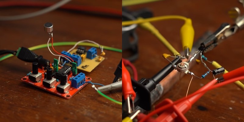
The next attempt was with a XR2206 function generator kit, which worked quite well when combined with a simple microphone amplifier circuit. But this time the receiving side was swapped out, as [GreatScott] built a basic circuit around a TA7642 AM amplifier/demodulator IC, with only six passive components and a hand-wound coil.
There is no shortage of ways to build AM radios, and we’ve covered quite a few over the years. Off course a 555 timer can also be used in a receiver, and building transmitters using only discrete components is quite simple, as demonstrated by the 10-minute transmitter and single transistor transmitter.


Interesting article, Danie. It does need a serious once-over by an editor, though.
Some extra reading:
https://www.radioworld.com/tech-and-gear/find-your-modulation-sweet-spot
https://sound-au.com/articles/am-modulation.htm
http://www.mf2fm.com/zfm/transmitter_circuits.php
Actually, AM is a mixing process. It mixes audio with the carrier, which results in a radio signal that follows the audio signal.
Since the modulator is unbalanced, the carrier just feeds through to the output.
Because it’s a mixing process, the output has the carrier plus audio, and carrier minus audio. That creates the two sidebands, identical to each other. It’s tge same thing as the image in a superheterodyne receiver.
The carrier never varies in amplitude. The illusion comes when an RF meter is put on the output, it can’t discriminate, so it looks like the power goes up and down (it’s really the sidebands).
At the receiver, the detector is mixing they sidebands with the carrier, to convert the sidebands back to audio frequency. Take away the carrier, and you wouldn’t get proper demodulation.
Thanks for that explanation, it was new to me. Would you be able to see the constant carrier power on a spectrum analyzer?
The carrier power would not appear as constant on a spectrum analyzer if the modulating signal were a square wave and the averaging period of the analyzer were much shorter than the square wave period. Also, at 100% modulation, the minimum power out would be zero and the maximum would be 4 times the nominal. It’s simpler to think of voltage instead of power: at 100% modulation the minimum voltage out is zero, the maximum is 2 times the nominal.
Although using the term “mixing” is technically correct, it is ambiguous. An audio mixer is strictly linear; the mathematical operation is addition. A radio frequency mixer requires multiplication to produce heterodyned output frequencies, and that multiplication occurs either from a nonlinear response or from a circuit designed to multiply 2 waveforms.
If one of the sidebands was inverted when broadcasting and then inverted again before mixing could that be used to decrease noise in the signal? For example, the signal is transmitted with one inverted sideband and lighting introduces noise into the transmission, when the sideband is inverted again the original signal will be normal but the induced noise in the mix would be eliminated because of the inversion? Does that make sense or do I need to stop drinking?
My first am transmitter was with one of the 101 science experiment kits with the coil held wiring boards from radio shack back when I was around 8 years old. I picked it up with some old spherical shaped am radio to hear the keyed beeping. I had almost forgotten all about that until this article. Good times. I seem to remember it had a range of about 10 – 15 meters. It was almost another lifetime ago. Thanks for the memories. :)
When I think of a simple silicon-based oscillator for even low-frequency RF work I never even consider the 555. I go for the 74HCU04 hex unbuffered inverter. They make good, simple oscillators based on crystals, resonators or L-C components. They can be biased into decent linear operation and pressed into service as linear amps from audio through a substantial number of MHz. They can be paralleled for better drive capability. Plus, you get six of them in a 14-pin package.
They’re just high gain amplifiers, at the end of the day. So what if the nominal use case is to rail them, stick a suitable feedback resistor on there and go analog! Or so I’ve heard anyway. Two things I wonder about, though, when they in that ‘forbidden zone’, is how linear are they, and what does it do to power dispassion?
If you used an XOR just right, it’d kind of do what an RF mixer does. Albeit with harmonics galore.