Metal 3D printers are, by and large, many times more expensive than their FDM and resin-based brethren. It’s a shame, because there’s plenty of projects that would benefit from being able to produce more heat-resistant metal parts with additive fabrication methods. [Integza]’s rocketry projects are one such example, so he decided to explore turning a MIG welder into a 3D printer for his own nefarious purposes. (Video, embedded below.)
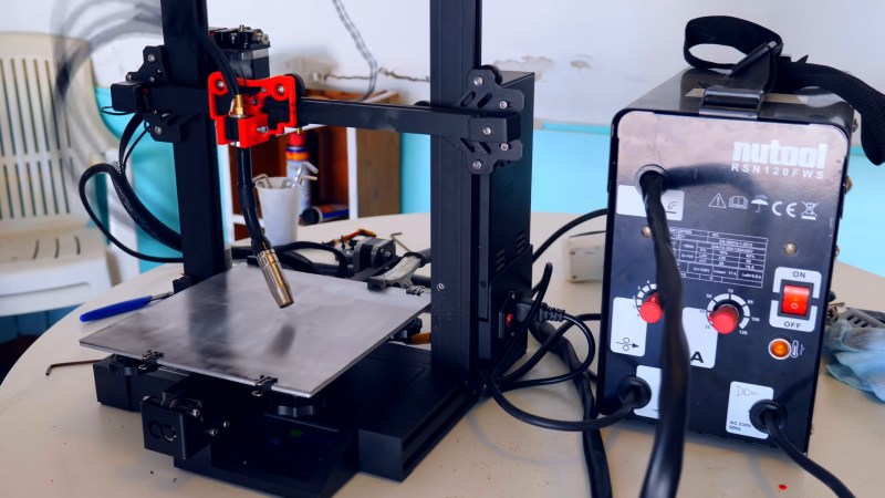
The build is as simple as you could possibly imagine. A plastic adapter was printed to affix a MIG welding nozzle to an existing Elegoo Neptune 2 3D printer. Unfortunately, early attempts failed quickly as the heat from the welding nozzle melted the adapter. However, with a new design that held the nozzle handle far from the hot end, the ersatz metal 3D printer was able to run for much longer.
Useful parts weren’t on the cards, however, with [Integza] facing repeated issues with the steel bed warping from the heat of the welding process. While a thicker steel base plate would help, it’s likely that warping could still happen with enough heat input so more engineering may be needed. It’s not a new concept by any means, and results are typically rough, but it’s one we’d like to see developed further regardless.


It’s probably going to require a full-on heavy welding table as a building platform, probably wouldn’t hurt for the surface being printed on to have multiple threaded studs welded on the underside, so that it can be bolted to the table to reduce warping. After printing those can be ground off.
Normally you could use clamps to reduce warping, but those could get in the way of a print head, so it’d be better to bolt things from underneath.
So if this was in an airtight room with only inert gas present and a cooling medium with high thermal conductivity it would eliminate slag and warping. How does mineral oil respond to welding in an oxygen free environment?
Spark erosion is sometimes done immersed in oil. I used to work somewhere with one that was filled with what we call “paraffin” but might also be known as Kerosene. The sparks and molten metal are on a smaller scale than welding, but the temperatures are probably the same. As long as the sparking is below the surface there is no problem. If the level gets low you get a very sooty fire.
Seems like a ceramic base would be best.
Oh he is going to have so much fun with warping base material.
Used to build MIG and laser based industrial additive manufacturing machines with 6 axis robots and warping always was an issue.
With small samples like he is doing, 50-60mm base material should be enough to counteract most of it though. won’t help you though, once you reach 500mm+ part diameters. Forces at work there sure are fun.
I was thinking the exact same thing.
I disagree. Buy incorporating a layer of water cooling into the base, all base heat issues subside.
Now this is a 3d printer I wouldn’t take my eyes off while it’s printing! Talk about a hazard.
Then you will be going blind.
Now that’s a proper hack
My thought was that this probably won’t ever work in any useful fashion in the direction he is going. He has to grind, BY HAND, each layer after welding to remove the slag. Sometimes he’s going to get too much, others, too little. It’s definitely not repeatable results. He’d need to add a grind wheel to some sort of tool change system if he’s going to continue in that direction. However that system would also need to take into consideration the wear on the grinder and it’s diminishing distance from the working surface after each pass. Possibly calculable, possibly measurable, not desirable. A better working space would be airtight and filled with inert gas. That quickly leaves the realm of cheap reprap style machines. He certainly should have waited to do this video until after he had the proper materials, but he claimed cost and time as prohibitive, but I’d say failure of such a magnitude is a quicker path to prohibitively expensive than just buying some thicker steel. I also couldn’t believe he left the glass bed on there, and in the video it looks like he did it AFTER seeing the heat trouble. Maybe that’s an editing artifact, maybe a mistake.
Anyway, here we are again, posting every single Integza video as an article. Yes they’re all good, but I already subscribe to him and watched this a week ago. You guys should really consider a YouTube section, or at least a weekly/monthly roundup article.
If he had a gas bottle instead of flux core welding wire he would have no slag to deal with. I have seen this done before with an NC router and a mig whip. It is a feasible concept, if you don’t need to worry about the immense internal stresses it will suffer from.
So heat up entire item in an oven to a certain point, then slowly cool down.
yep, but it’s 600C at least for a good stress relieving, not your everyday oven.
Would using an aluminum welder bring down the heat instead of a traditional mig
Sparky
All metal needs stress relieving to avoid warping one method commonly used water we have used water pipes welded to bus bars for crucible Furness
In a oil refinery we used electric elements embedded in porcelain for pipe welds we had sensors monitoring the situation if a element went down we had to replace it gradually the temperature would be reduced to ambient
Or run the printer in an argon atmosphere.
My thoughts exactly.
Just seal the whole thing in a box and fill it with an inert gas.
Or maybe an inert liquid?
@Andy: There is a reason “MIG” means “metal inert gas” welding. A liquid would either cool the thing too much or just vanish in a series of steam explosions at 3500°C of the arc.
But why not use just argon like in the original welding application?
Is that what they do welding radiator cores
That would be my suggestion as well , we do that in high purity work , but he needs to go to a tig process with a wire feed like they do with the orbital pipe and tube welding systems, that way as the material gets hot he could cut back on the amps
Need to use pulse mig, less heat introduced into material, no spatter when set properly and faster feed speed. Pulse also allows vertical and underside (known as overhead in the industry).
Could probably use a needle scaler tool instead of a grinder.
I think you need to look at his guy’s YouTube channel. Failure and then try again is his normal working approach. It’s the journey that counts!
https://www.youtube.com/watch?v=lJQjszI_vfM&ab_channel=EuroTrade ?
Using a mig welder as a metal 3d printer totally works. Here’s a chair that I “printed” about 5 years ago https://www.carlbass.com/elbochairsteel.html
This is incredible! Great work.
Very cool- was this robot already setup with a welding package or was there anything specific you did to set the bot up? I’ve been wanting to use the robot arm I have access to do some mig torch printing or as a “third hand” for positioning parts at odd angles but I’m a bit terrified of shorting 220 into it.
The voltage between the MIG torch head and the “grounded” base material is generally in the low 10s of volts. Lots of amps, however, so caution is still advised. Also, even with DC welding, you are likely to get lots of EMF noise that can affect sensitive nearby electrical components.
Wow. That is beautiful!
Welding hat tipped. That’s, awesome!
That video is awesome. And thank you for your contribution for the maker movement and the residency program.
Fail of the week?
Lol the guy who said ceramic base doesn’t understand how a welder works I guess
I assume the ceramic base would be to protect the actual bed of the printer for the heat, under the actual metal being welded to.
Ok the point was to keep it cheap and simple guy adding gas is just gonna make it that more complicated and cost more especially over time
The CO2 mix that mig welders use is surprisingly cheap
Tip for you sir when you said” they hold it at an angle….” That technique is more for when welding with a rod your angle will not matter In this case as much as your amp and wire feed speed (rhyme time)
3d print me a exact copy of your sweet mustache. I need it
I’ve been a professional welder for over 16 years…it’s possible… He should have used a pulse welding machine for starters. No flux core. Could’ve used aluminum plate as a bed…I really could go on for days on this…
Doesn’t flux core make it not mig?
Could you please do a write-up for those of us that are interested in persuing this?
You can check out several ways we did this a few years ago. But basically we took a commercial MIG welder and hooked it up to a bunch of servos to move it (in the video we hooked it up to a robot arm). The trick was knowing when to move forward. We used some fiber optics to look at the molten metal and when the puddle was big enough, it would reflect light back to our sensors and we would move forward. You can see the chair we printed at https://www.carlbass.com/elbochairsteel.html
This is such an obvious idea that I have always assumed that if it could be made to work, the world would be full of them.
It has been done using powder filler and laser melting. Search for the “DMG Mori Lasertec”
But MIG never seems to work.
Welding is a method of joining two similar metals together and in some cases to dissimilar metals. The common theme of welding is that the filler material is very similar to the metals being bonded.
There are other methods like chemical welding, brazing, cold welding and even welding under water! This is often done to repair ship hulls.
The main requirement of welding things like buildings, pipelines and the likes of bridges is that the welding equipment needs to portable and the welding is most likely going to be done in free air.
When the oxygen in free air becomes a problem we add inert gasses like argon which is expensive and doesn’t tend to hang around for long resulting for a need for continuous flow.
This form of 3D printing may well have a great deal of potential of the so called “welding” process was immersed in a liquid where the chemical properties could be easily controlled and optimized for a 3D printing process rather then a more traditional “welding” process.
My 2c anyway.
+1
Welding is a known process of joining materials since 1840 or so. Welding steel is a known process since the invention of steel and today very well known and understood.
That said, additive manufacturing is a manufacturing process with a high demand. Everyone and their mother would love to have such a process to replace some steps of machining.
Fused Filament Fabrication with metal? Does it exist beside some prototypes in some labs? I don’t think so. I would assume that mothers would throw tons of money at them if there is any usable progress…
/me just fishing.
It’s an entertaining way to ruin a 3D printer, I’ll give him that.
Pretttvyyy sure there’s all kinds of fanuc, Panasonic, ect robot welders out there. I used to program them. I mean it’s really just the same thing. Instead building what ever with points with the controller, your feeding it points via a program. Its all one in the same. Id say stick to the original way of building and programing robot welder arm and programing just do it on a mini scale. You would need a nice 1″ – 2″ thick steele table top, and I would use a boring mill or a bridge port and make the top like a 1 2 3 block with threaded holes spaced out. That way you can secure any thing you want any away would want. And not have clamps all over and what not. Plus if you harden the table after milling it you should never ever have an issue. Its not like your making a 20ft fab table were only talking like 2ft² . Unless you just use a normal robot welder then.. drop the 3d printer and use an adrino and a few servos and build a small robotic welding arm. You could even make it travel on x and y plain. And cost for parts is next to nothing. Considering you already have a welder and make most of what you need. There is pleanty of open source free cad, 3d programs, and pcb building programs out there also. I know a whole bunch.
The way feronious builds their welders keeping it cool is key. And you need to be running with shielding gas. At a speed that is slow enough to weld layers and get good penitration with out porosity, but not so slow that your puddling the layer below collapsing it. It can get complicated in areas of weld affecting different areas of the build. Settings and heat, amps, will constantly have to be changing to make the welder weld right when accommodating the build. Thats why I say stick with robot welding arm area and tweak what ever you need.
I support experimentation, and projects for fun, but this is a really poor attempt to share and feels quite clickbaity, this is first proof of concept, low effort stuff that anyone can do with 24h of work.
MIG can do pretty good quality “3D printing”, you just need to get at least the ABCs right, don’t even attempt it without gas, with a torch that’s not orthogonal to the surface… This is the bare minimum to start experimenting and getting good quality results out of cheap-ish equipment.
Yes , but his purpose beas to gather our greatest out puts to help lead him in a direction closer than what he’s achieved
I find something incredibly off-putting in this guy’s flawed Tesla imitation.
I don’t know who tried this first but I remember watching a bunch of videos of students at Michigan Tech 3d printing metal this way though they built something much more robust than simply attaching a welder to a regular 3d printer. I can’t believe the printer survived as well as it did! I expected it to be destroyed on the first attempt.
I meant to add, I think their attempt was pretty early, almost back to the repraps being made in user-groups days.
What it needs is a really thick stationary build plate with a core XY gantry bolted right to it. The bed surface should have a file-like rasp texture that is purposely surface rusted. That way one good hammer/chisel strike with knock your print loose.
Something like this might make for a better print head…
https://lasersystems.ipgphotonics.com/en-US/products/Handheld-Systems/Handheld-Laser-Welding-System
I think a thick enough weld plate perhaps 3/4 jetted to allow coolant in and out at the perimeter cause heat transfers outwardly. You still need enough heat to not create crystalization. Experimenting to get the right temp will be the issue . That’s the most I’m gonna give it my idea
Great idea. Just vary the coolant flow via a temperature gauge to maintain a target temperature.
Using gas with shorter bursts without cutting gas would help a lot
A sacrificial sheet metal surface on top of an insulator bed, like pure stainless steel (or steel sandwiching firebrick) would be needed. It is not that hard to figure out the proper materials to protect the temperature sensitive bits, but the hard part is also making sure the part doesn’t cool too quickly to prevent your print from being F’ed.
This was done better with an inverted delta printer in 2013:
https://www.appropedia.org/Open-source_metal_3-D_printer
It would make good sense to use two part adhesives with similar qualities. Less heat and less chance of fire. Yet rigid and durable. Go!
Have you considered water cooling a thick steel or stainless plate? Get a plate about 1″ thick or so, bore a bunch of 1/2″ hols through (or whatever, the holes should probably be spaced by 1/4″ edge-to-edge and be 1/4″ below the working surface.) and run water or anti-freeze/coolant solution through the plate.
this old toby did that long time ago
Rocketdyne (Nozzles), Rotterdam harbour (Alloy printed Brass Proppeler for TugBoat), ETH Zürrich (model of rocket engine combustion chamber with honeycomb cooling orrificies), and recently US launched RocketLab (Whole Rockets with 90% reduction in time and asembly labour until launch)..
Correct me if claimed wrong..
All of them (and Many more) using all but some kind of “spot sintering” technique, istead of “layered sintering”.. I may wrongly suggest, but all of them are using some Innert gas proccess, with Gantry or Arm setups.. All of spot additive technologies feeding Wire/Flux to spot..
Personaly i whould prefere TIG (tungsteen electrode arc) and Wire feeder option.. Though @Raymond Stewart link: https://lasersystems.ipgphotonics.com/products/Handheld-Systems/Handheld-Laser-Welding-System is unbeatable in performance, just price..
I never thought about attaching my mug welder to my old printer, but I certainly have thought about attaching my plasma cutter to it. Maybe now I’ll try it, I’ll just have to be sure not to cut through the bed, lol.
BTW, g-codes certainly can make curves. Give it an x,y,z start point and an x,y,z end point, and a CenterPoint. It’ll do it.
Seems like it could get a lot of splatter first of all. Everything important should be shielded…
Heat may not be a problem if you alternate printing from one side to the other with series’of small tacks. Instead of long beads as one would like for spreed., But they will warp for sure.
Good ideas,
Add it to a big lathe and you can automate shaft repairs..
Yeah, many minutes of blah-blah interspersed with multiple in your face WOKE ads, and I never got to see the thing actually print anything. I just moved on in disgust.
Hello,
I am currently working on a similar project where I am trying to do TIG welding based 3d printing. However I am not using a 3d printer as a base and because of this I do not know how to go about finding the code for the same. Requesting your help for the same, if you could share the code you used or if you have an open source code for such a process it would help tremendously
thanks you